Gyroscope with phase and duty-cycle locked loop

a phase and duty-cycle locked loop technology, applied in the field of gyroscopes, can solve the problems of reducing reducing the accuracy of the gyroscope, and reducing the noise of the gyroscope, so as to improve the noise performance of the gyroscope, improve the bias stability, and reduce the footprint

Active Publication Date: 2013-04-25
INVENSENSE
View PDF4 Cites 77 Cited by
  • Summary
  • Abstract
  • Description
  • Claims
  • Application Information

AI Technical Summary

Benefits of technology

[0004]A system and method in accordance with the present invention provides a gyroscope based on an improved phase locked loop (PLL) technique. The improved PLL auto-corrects its own reference low-frequency noise, thereby eliminating this source of noise, improving the noise performance of the gyroscope and allowing a compact implementation. The net result is a gyroscope with improved bias stability that can meet noise requirements with a smaller footprint.

Problems solved by technology

Such PLL's are vulnerable to low-frequency jitter which arises due to phase modulation of a sinusoidal reference clock source when noise is added to it.
This additive noise is converted to duty-cycle error, and subsequently phase noise, when the sinusoidal reference clock is converted to logic levels by a comparator or similar circuit.
This becomes a serious limitation when a conventional PLL is used in the demodulator path of a rate gyroscope.
However, such techniques suffer from low-frequency noise added by the duty-cycle measuring circuit.

Method used


Image

  • Gyroscope with phase and duty-cycle locked loop
  • Gyroscope with phase and duty-cycle locked loop
  • Gyroscope with phase and duty-cycle locked loop

Examples


Embodiment Construction

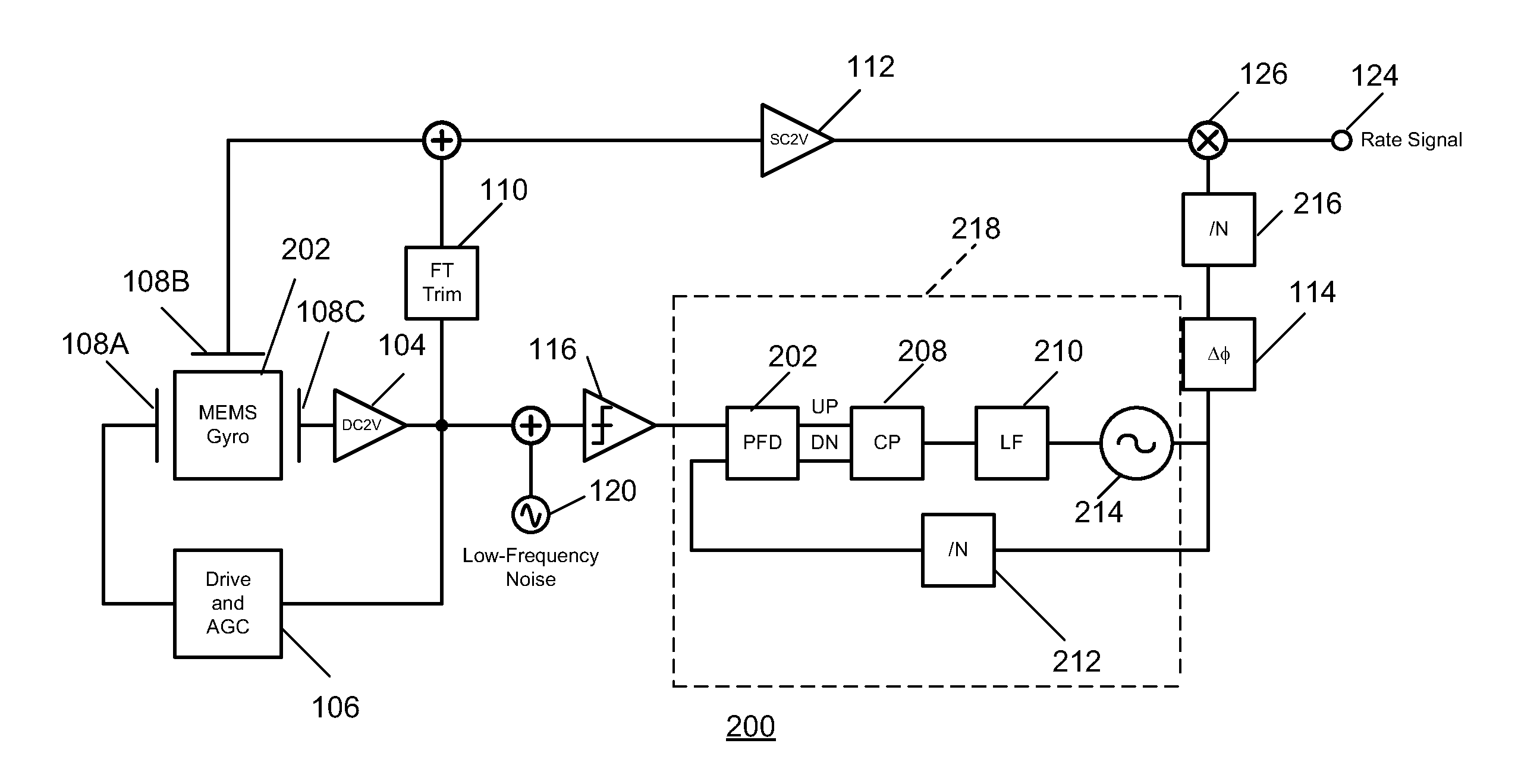
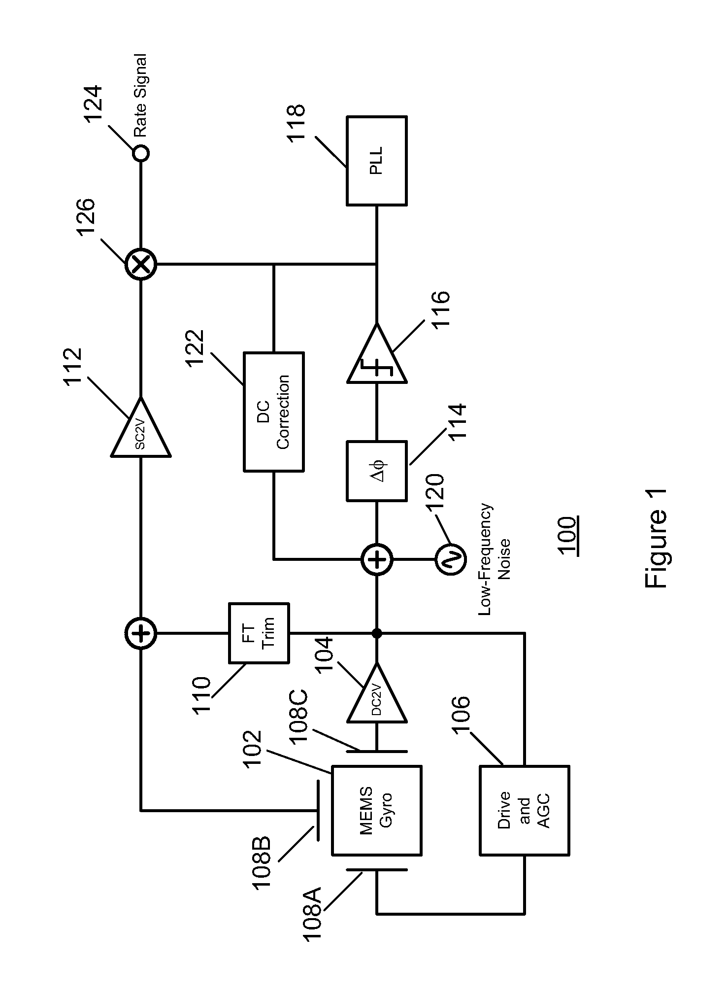
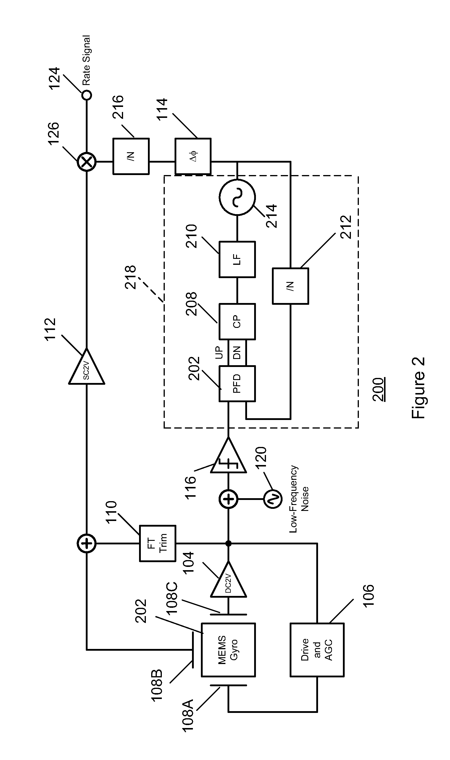
[0014]The present invention relates generally to gyroscopes and more particularly to phase- and duty-cycle-locked loops utilized in gyroscopes. The following description is presented to enable one of ordinary skill in the art to make and use the invention and is provided in the context of a patent application and its requirements. Various modifications to the preferred embodiment and the generic principles and features described herein will be readily apparent to those skilled in the art. Thus, the present invention is not intended to be limited to the embodiments shown but is to be accorded the widest scope consistent with the principles and features described herein.

[0015]A system and method in accordance with the present provides the following features:[0016]Phase comparison operates on both edges of the clock, so that the effect of additive noise on the timing of those edges is averaged out in the PLL. Thereby, conversion of additive low-frequency reference noise to phase noise ...


PUM


Abstract

A system and method in accordance with the present invention provides a gyroscope incorporating an improved PLL technique. The improved PLL auto-corrects its own reference low-frequency noise, thereby eliminating this source of noise, improving the noise performance of the gyroscope and allowing a compact implementation. The net result is a gyroscope with improved bias stability that can meet noise requirements with a smaller footprint.

Description

CROSS-REFERENCE TO RELATED APPLICATION[0001]Under 35 U.S.C. 119(e), this application claims priority benefit to U.S. provisional application No. 61 / 551,314 filed on Oct. 25, 2011.FIELD OF THE INVENTION[0002]The present invention relates generally to gyroscopes and more particularly to gyroscopes employing phase- and duty-cycle-locked loops.BACKGROUND OF THE INVENTION[0003]Conventional phase-locked loops (PLL's) utilized in gyroscopes use a single edge of the reference clock for phase comparison. Such PLL's are vulnerable to low-frequency jitter which arises due to phase modulation of a sinusoidal reference clock source when noise is added to it. This additive noise is converted to duty-cycle error, and subsequently phase noise, when the sinusoidal reference clock is converted to logic levels by a comparator or similar circuit. This becomes a serious limitation when a conventional PLL is used in the demodulator path of a rate gyroscope. Conventional duty-cycle correction methods woul...

Claims


Application Information

Patent Timeline
Patent Type & Authority Applications(United States)
IPC IPC(8): H03L7/08G01C19/04
CPCG01C19/5776H03L7/089Y10T74/12H03L7/08H03L7/0893
Inventor SHAEFFER, DEREKSOUKHAPHANITH, AHINGSA
Owner INVENSENSE
Why Eureka
Try Eureka