Method and apparatus for supporting network-based flow mobility

Inactive Publication Date: 2013-04-25
ELECTRONICS & TELECOMM RES INST +1
View PDF7 Cites 3 Cited by
  • Summary
  • Abstract
  • Description
  • Claims
  • Application Information

AI Technical Summary

Benefits of technology

The present invention provides a solution for a Multi-Mode Network (MN) which has multiple network interfaces and can connect to both wired and wireless networks. The invention includes a location registration procedure for each flow, a procedure for transmitting flow-based data, and a procedure for performing handover for each flow. Additionally, the invention also provides a method for managing binding information, transferring control messages, and operating a network using flow-based mobility control technology. These technical effects improve network mobility and provide a better user experience for mobile users.

Problems solved by technology

Furthermore, if a specific interface is not capable of communication due to reasons, such as a movement of an MN or the quality of a network, data flows that use the specific interface have to be redistributed over other interfaces.
This method, however, is problematic in that necessary service flow binding is requested only when data traffic of a new service flow, that is, uplink packets, is transmitted from an MN to an MAG and this service flow binding cannot be requested when the traffic is transmitted from a Corresponding Node (CN) to a corresponding MN.
The method proposed by this article is problematic in that a user who uses an MN actually lets management for each flow to be performed on the basis of only static and previously stored information irrespective of desired preference.
Like the method (2), this method is problematic in that dynamic user preference cannot be incorporated because this method depends on the static profile of an MN or the policy of a service provider and thus generates the handover of a service flow.

Method used


Image

  • Method and apparatus for supporting network-based flow mobility
  • Method and apparatus for supporting network-based flow mobility
  • Method and apparatus for supporting network-based flow mobility

Examples


case 1

[0145] Flow Mobility Procedure According to New Connection of Mobile Terminal

[0146]FIG. 12 shows a flow mobility procedure according to the new connection of a mobile terminal in accordance with the present invention.

[0147]Referring to (a) of FIG. 12, an MN transmits and receives a flow 1 and a flow 2 through a HCA#1 using a WLAN PI1 interface from among physical interfaces owned by the MN. Here, it is assumed that the flow ID of the flow 1 is 4 and the flow ID of the flow 2 is 3. In this case, a flow binding table and a session information table managed in an MICS may be shown as below.

TABLE 11FlowBindingLife-IDPriorityFlow SelectorIDsTypetime44(IP2, *, 21, *, *)WL→3G→WBStatic∞33(*, *, 150, *, UDP)3G→WL→WBStatic∞22(*, FF01:: / 64, *, *, *)WL, 3G, WBDefault∞11(The(*, *, *, *, *)3G→WL→WBDefault∞lowest)

TABLE 12FlowBindingLife-IDPriorityFlow SelectorIDsTypetime44(IP1, *, *, 21, *)WL→3GStatic∞33(*, *, *, 150, UDP)3G→WLStatic∞22(*, FF01:: / 64, *, *, *)WL, 3GDefault∞11(The(*, *, *, *, *)3G→W...

case 2

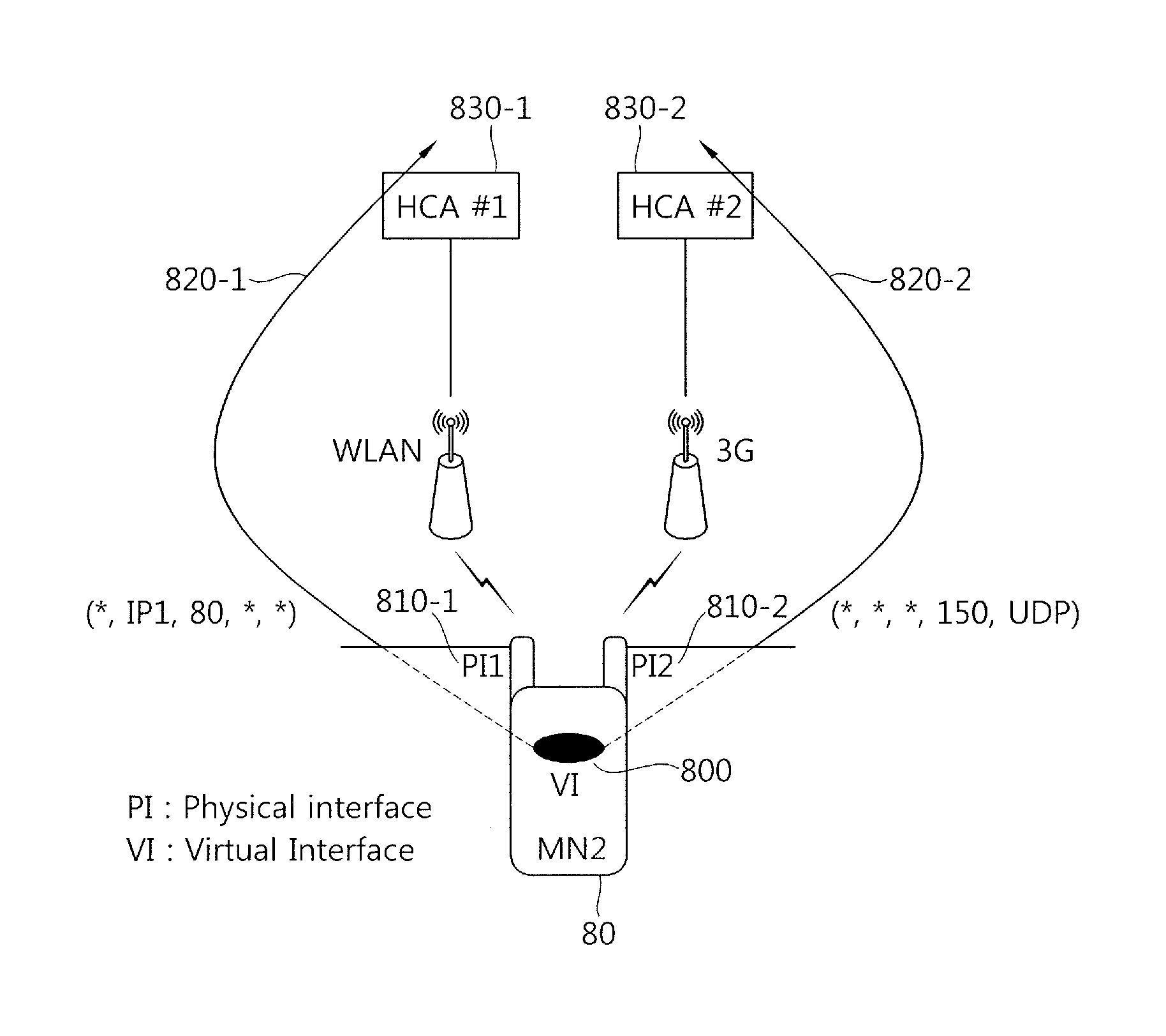
[0164] Flow Mobility Procedure According to Independent Determination of MICS

[0165]A network side in which an MICS operates as described above can check the state (e.g., whether a link operates or not, a congestion status, the number of terminals being served, and the number of flows) of wired / wireless links. Accordingly, a flow can be moved at a specific point of time under the determination of the MICS. In this case, characteristics are as follows.

[0166]From a viewpoint of a recipient node (e.g., an MN2 or CN) that receives an inbound flow, an MICS can move only the inbound flow received by the recipient. That is, an MN (e.g., an MN1) determines that an outbound flow will be transmitted through what interface, and the MICS may change the inbound flow so that the inbound flow is received through another interface (or another network) from a viewpoint of a recipient that receives the inbound flow. Even in this case, however, if the outbound flow transmitted by the recipient node is ...

case 3

[0177] Flow Mobility Procedure According to Determination of MN and Permission of MICS

[0178]When a terminal itself tries to move some of flows, now being exchanged, from a current interface to another interface, an intention of the terminal may be transmitted to an MICS via a HCA and the MICS may determine suitability for the flow movement of the terminal according to circumstances. In this case, if the MICS determines that the flow movement is suitable, the terminal can move the flows as in a common location registration procedure. This has the following characteristics.

[0179]In Case 3, from a viewpoint of a sender node that sends a transmission flow, only a transmission flow can be moved. That is, an MN that sends a transmission flow has to determine whether a transmission flow will be transmitted through what interface and inform an MICS of his intention. If the MICS determines that the transmission of the transmission flow is suitable, the MN sends the transmission flow to an in...


PUM


Abstract

The present invention relates to a method and apparatus for supporting location registration and mobility for each service flow in relation to a Mobile Node (MN) having a plurality of wired / wireless network interfaces in a wired / wireless integrated network environment. A method includes receiving a location registration message from a specific Handover Control Agent (HCA) connected to an MN, determining a movement of a flow, configured in another HCA to which the MN is connected, based on predetermined static flow binding information or a network status, sending a location registration Ack. message, comprising information on a HCA in which the flow is configured and to which a Corresponding Node (CN) is connected, to the specific HCA, and sending a location notification message, comprising information on the specific HCA to which the flow will be moved and to which the CN is connected, to the HCA.

Description

[0001]Priority to Korean patent application numbers 10-2011-0108972 filed on Oct. 24, 2011 and 10-2012-0101706 filed on Sep. 13, 2012, the entire disclosure of which are incorporated by reference herein, is claimed.BACKGROUND OF THE INVENTION[0002]1. Field of the Invention[0003]The present invention relates to networking and, more particularly, to a method and apparatus for supporting location registration and mobility for each service flow in relation to a Mobile Node (MN) having a plurality of wired / wireless network interfaces in a wired / wireless integrated network environment.[0004]2. Discussion of the Related Art[0005]At the present time, not only wired communication techniques, such as Ethernet and Fiber-To-The-Home (FTTH), but also a variety of radio access techniques, such as a Wireless Local Area Network (WLAN), Wibro, 3G (e.g., CDMA), and 3.5G (e.g., HSPA), appear, and they are being provided to users. In line with a change in this communication environment, active research...

Claims


Application Information

Patent Timeline
IPC IPC(8): H04W36/00
CPCH04W36/22H04W36/32H04W60/005H04W36/005H04W40/36H04W8/02H04W80/04H04W36/322
Inventor LEE, KYOUNG HEELEE, SUNG KUENHAN, YOUN HEELEE, HYUN WOORYU, WON
Owner ELECTRONICS & TELECOMM RES INST
Why Eureka
Try Eureka