Opticalfiber temperature distribution measurement apparatus

a technology of temperature distribution measurement and optical fiber, which is applied in the direction of instruments, heat measurement, measurement devices, etc., can solve the problem of difficult to recognize accurate loss profiles

Active Publication Date: 2013-04-25
YOKOGAWA ELECTRIC CORP
View PDF4 Cites 36 Cited by
  • Summary
  • Abstract
  • Description
  • Claims
  • Application Information

AI Technical Summary

Problems solved by technology

In this case, an accurate loss

Method used


Image

  • Opticalfiber temperature distribution measurement apparatus
  • Opticalfiber temperature distribution measurement apparatus
  • Opticalfiber temperature distribution measurement apparatus

Examples


Embodiment Construction

[0038]In the following detailed description, for purpose of explanation, numerous specific details are set forth in order to provide a thorough understanding of the disclosed embodiments. It will be apparent, however, that one or more embodiments may be practiced without these specific details. In other instances, well-known structures and devices are schematically shown in order to simplify the drawing.

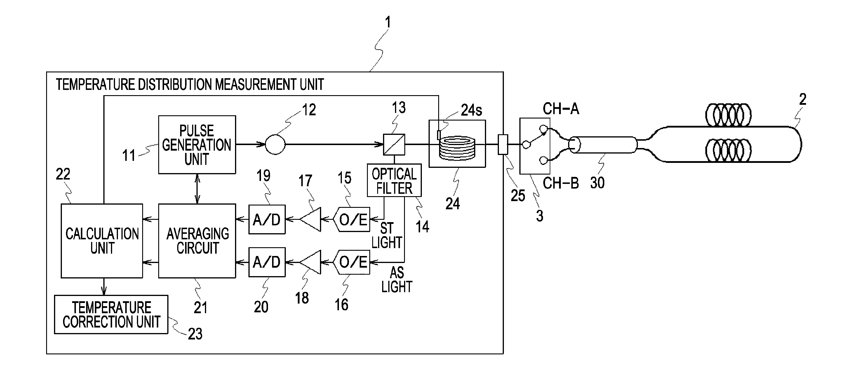
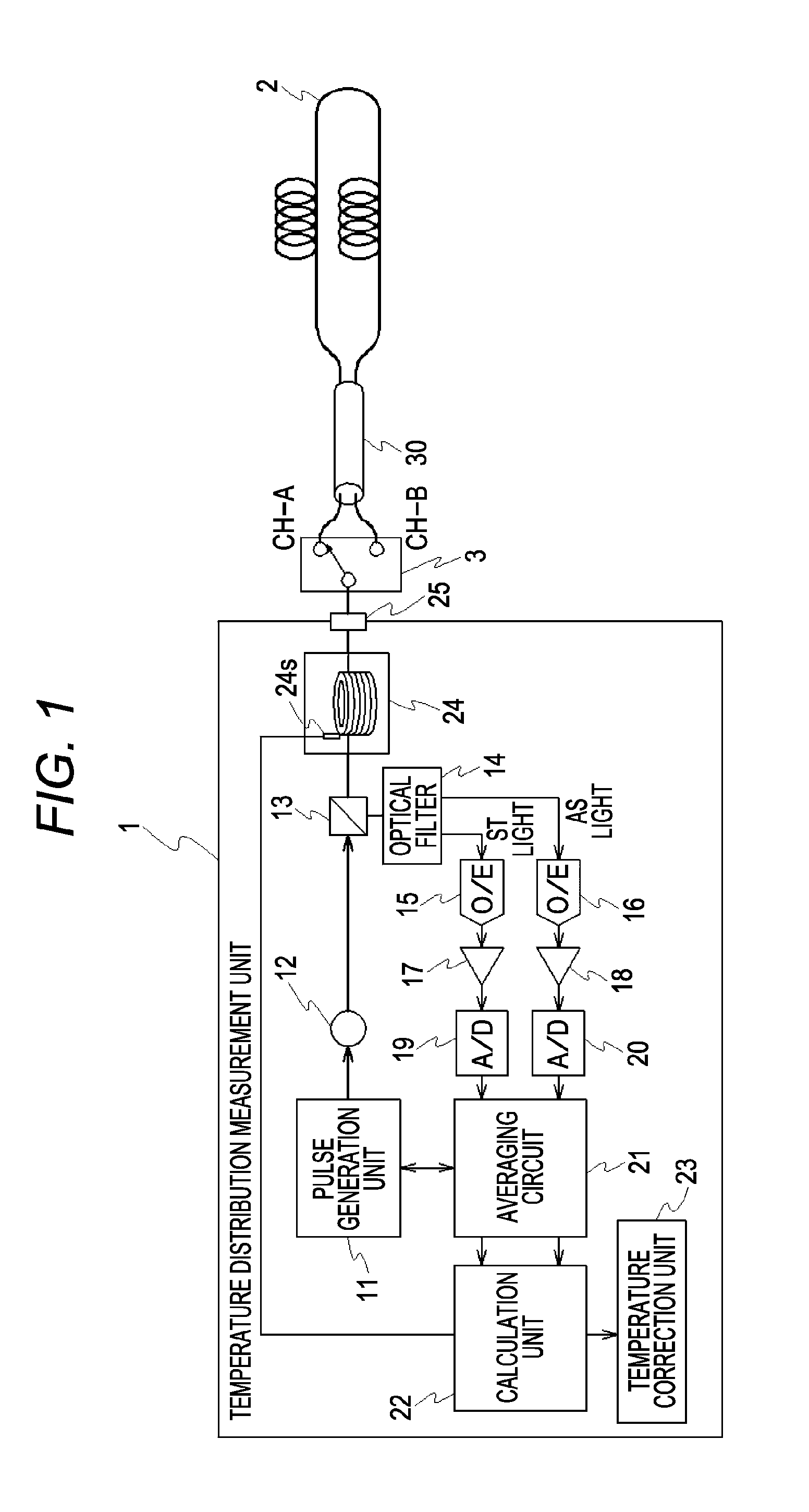
[0039]A phenomenon called “darkening” may be caused with respect to an optical fiber. If the darkening is caused, the Raman loss ratio in the optical fiber is changed. Accordingly, the above-described parameter Ltotal in Equation 3, namely, the Raman loss ratio with regard to the total length of the optical fiber 101 is changed. As a result, it becomes difficult to accurately measure the temperature distribution of the optical fiber 101 by the double-ended measurement.

[0040]An object of the present disclosure is to accurately measure temperature distribution along an optical fiber by...


PUM


Abstract

The present apparatus includes: an intensity ratio calculation unit configured to calculate a first and a second intensity ratios which are ratios of Stokes light intensity to anti-Stokes light intensity obtained when a light pulse is output to a first end and a second end of an optical fiber, respectively; a temperature calculation unit configured to calculate a temperature distribution along the optical fiber based on a reference temperature, the first and the second intensity ratios, and a total length loss ratio, which is a loss ratio of Stokes light to anti-Stokes light with regard to a total length of the optical fiber; and a total length loss ratio calculation unit configured to calculate the total length loss ratio based on the first and the second intensity ratios with regard to a location in a predetermined section close to both ends of the optical fiber whose temperature is kept constant.

Description

CROSS-REFERENCE TO RELATED APPLICATION[0001]This application is based on Japanese Patent Application No. 2011-232838 filed with the Japan Patent Office on Oct. 24, 2011, the entire content of which is hereby incorporated by reference.BACKGROUND[0002]1. Technical Field[0003]The present disclosure relates to an apparatus for measuring temperature distribution along an optical fiber by using Raman scattered light.[0004]2. Related Art[0005]A DTS (Distributed Temperature Sensor) has been used for measuring temperature distribution along an optical fiber. The DTS is an apparatus for measuring temperature distribution along an optical fiber by using backscattered light generated in the optical fiber. The backscattered light includes Rayleigh scattered light, Brillouin scattered light and Raman scattered light, for example. The Raman scattered light, which has strong temperature dependence, is used for temperature measurement. In the case of the temperature measurement by using the Raman sc...

Claims


Application Information

Patent Timeline
IPC IPC(8): G01K11/32
CPCG01K11/32G01K2011/324G01K15/005G01K11/324
Inventor AGAWA, HISAO
Owner YOKOGAWA ELECTRIC CORP
Why Eureka
Try Eureka