
Adjusting proximity thresholds for activating a device user interface

a technology of proximity threshold and user interface, which is applied in the direction of programme control, optical radiation measurement, machine learning, etc., can solve the problems of not having power storage means, difficult and costly direct hardwiring of a common “c” wire from the transformer to the electronic thermostat,

Active Publication Date: 2013-04-25
GOOGLE LLC
View PDF0 Cites 195 Cited by
  • Summary
  • Abstract
  • Description
  • Claims
  • Application Information

AI Technical Summary

Benefits of technology

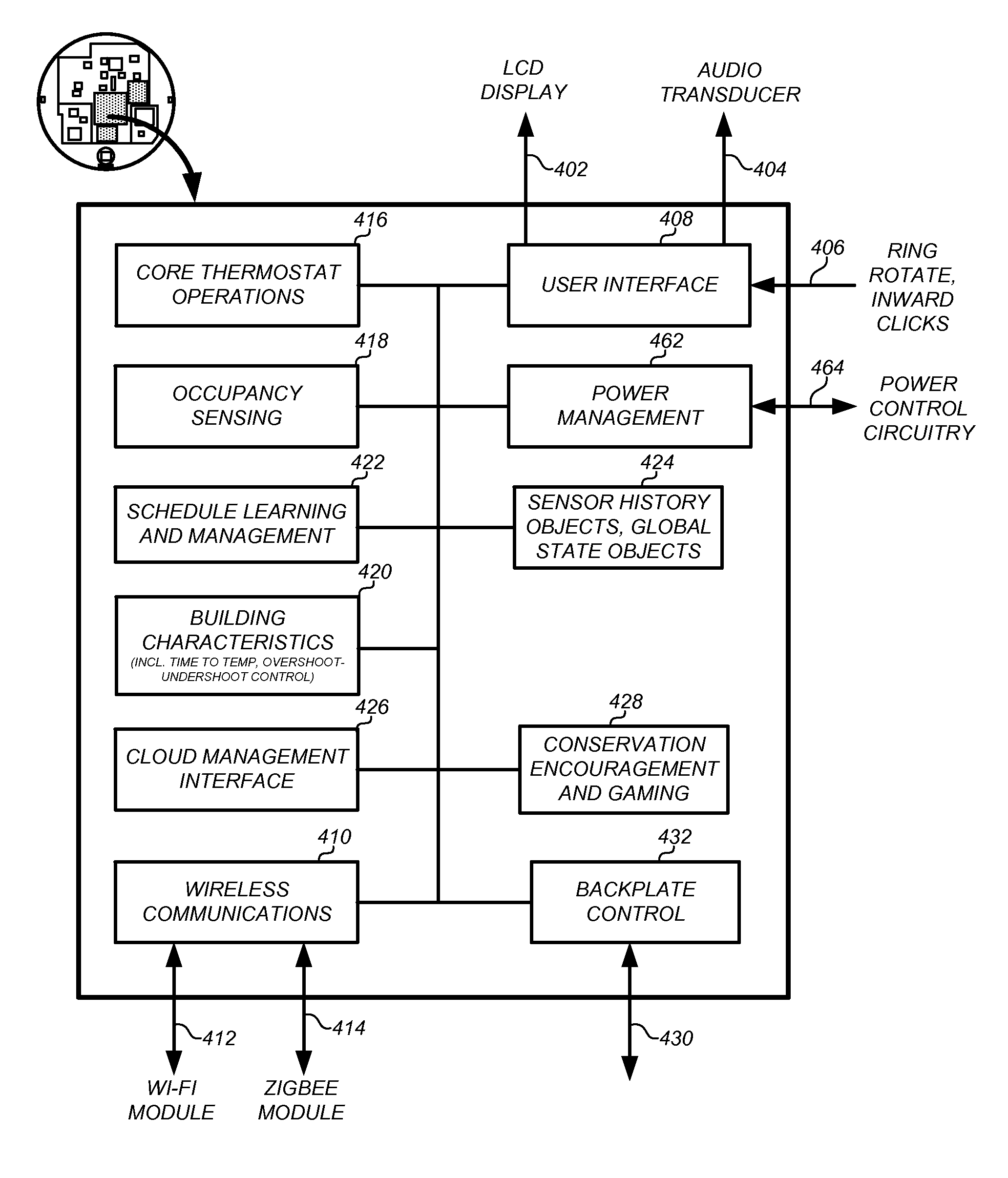
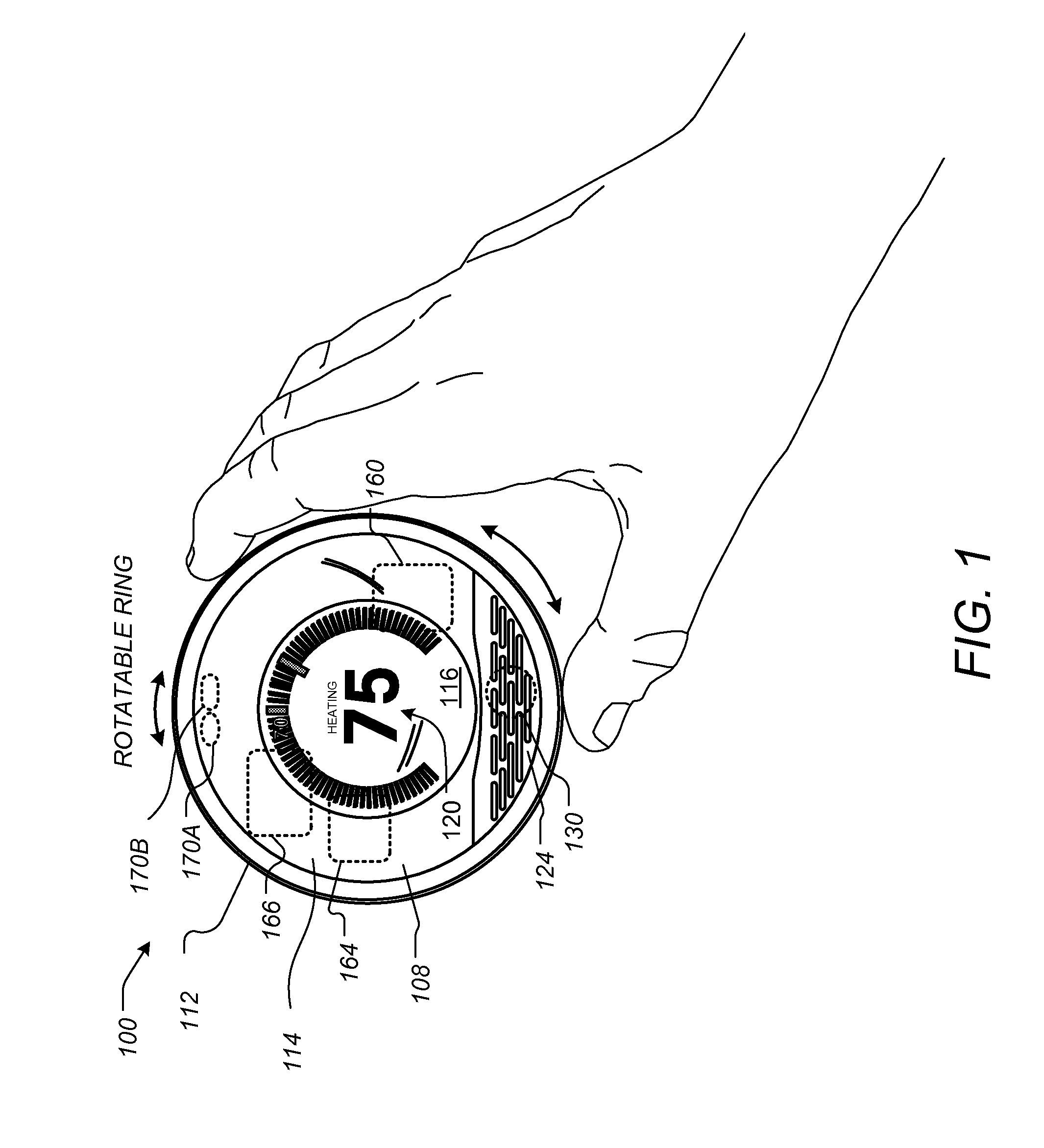
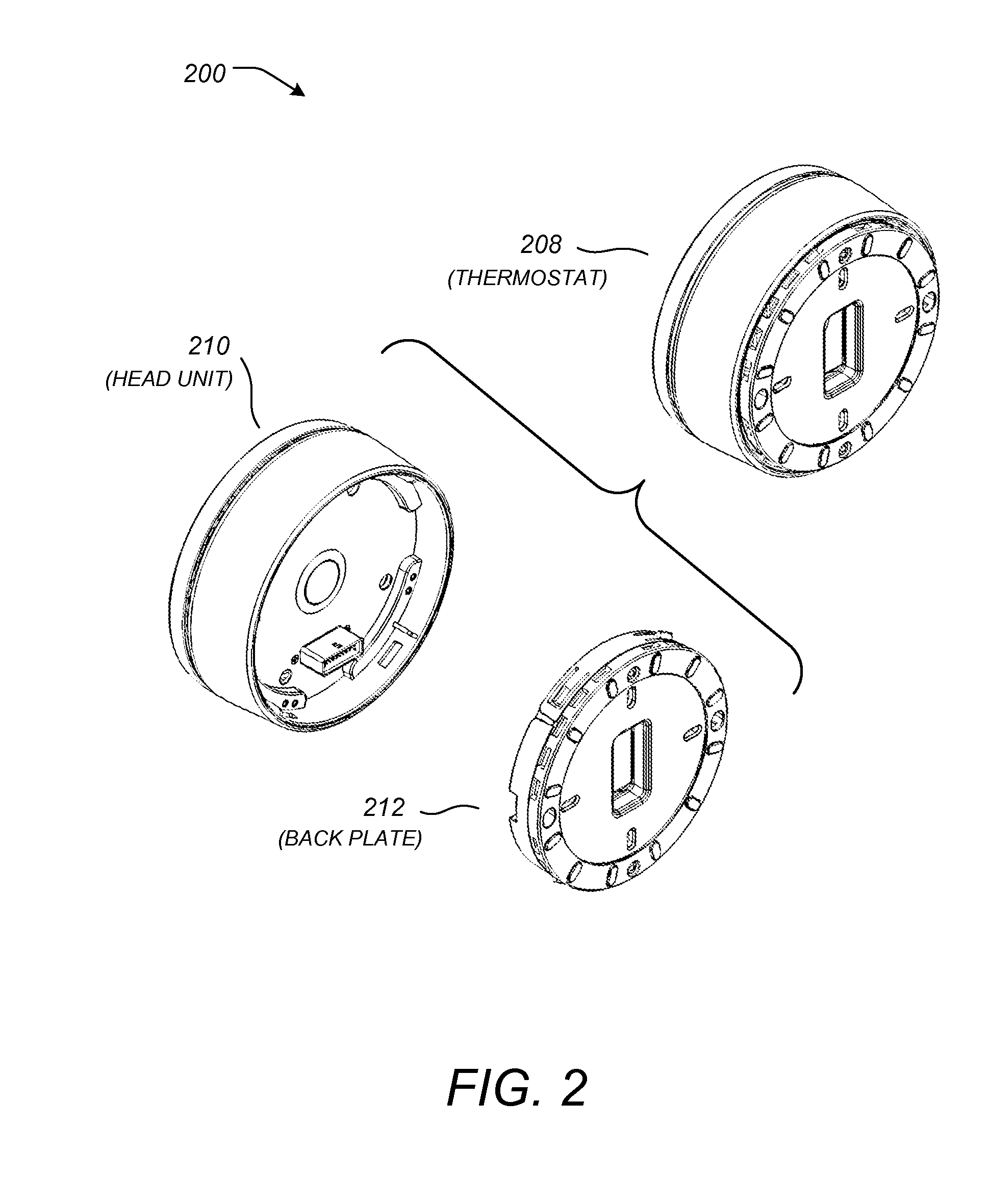
The present invention provides a thermostat with a user interface that includes a display and a processing system. The processing system is in communication with one or more temperature sensors and input devices for determining a setpoint temperature. The thermostat also includes one or more sensors to detect a user's physical closeness to the user interface, and the processing system adjusts a closeness threshold based on historical physical closeness events. The user interface can automatically transition from an inactive display mode to an active display mode upon detection of a user's physical closeness, which requires more power. This allows the user interface to display more information and make better decisions based on the user's wishes. The processing system also uses sensors to determine the user's proximity to the thermostat and adjust the display accordingly. Overall, the invention improves the user experience and optimizes the operation of the thermostat.

Problems solved by technology

When electronics began to be used in thermostats, the fact that the thermostat was not directly wired to both sides of the transformer for its power source created a problem.
Direct hardwiring a common “C” wire from the transformer to the electronic thermostat may be very difficult and costly.
However, these systems do not have power storage means and therefore must always rely on power stealing.

Method used


Image

  • Adjusting proximity thresholds for activating a device user interface
  • Adjusting proximity thresholds for activating a device user interface
  • Adjusting proximity thresholds for activating a device user interface

Examples


Embodiment Construction

[0040]The subject matter of this patent specification relates to the subject matter of the following commonly assigned applications, each of which is incorporated by reference herein: International Application No. PCT / US12 / 00007 filed Jan. 3, 2012; and U.S. Ser. No. 13 / 467,025 filed May 8, 2012. The above-referenced patent applications are collectively referenced herein as “the commonly-assigned incorporated applications.”

[0041]In the following detailed description, for purposes of explanation, numerous specific details are set forth to provide a thorough understanding of the various embodiments of the present invention. Those of ordinary skill in the art will realize that these various embodiments of the present invention are illustrative only and are not intended to be limiting in any way. Other embodiments of the present invention will readily suggest themselves to such skilled persons having the benefit of this disclosure.

[0042]In addition, for clarity purposes, not all of the r...


PUM


Abstract

A thermostat includes a user interface that is configured to operate in at least two different modes including a first mode and a second mode. The user interface may require more power when operating in the first mode than in the second mode. The thermostat also includes a plurality of sensors, including at least one sensor configured to detect a presence of a user within a proximity of the thermostat. The thermostat additionally includes a first processing function that is configured to determine a proximity profile and to cause the user interface to be in the first mode one or more sensors provides responses that match the proximity profile. The proximity profile may be computed using a history of responses from the sensors that are likely to coincide with times where users intend to view the user interface.

Description

CROSS-REFERENCES TO RELATED APPLICATIONS[0001]This application claims the benefit of the commonly assigned U.S. Prov. Ser. No. 61 / 627,996 filed Oct. 21, 2011, which is incorporated by reference herein.TECHNICAL FIELD[0002]This patent specification relates to systems and methods for the monitoring and control of energy-consuming systems or other resource-consuming systems. More particularly, this patent specification relates to control units that govern the operation of energy-consuming systems, household devices, or other resource-consuming systems, including methods for activating electronic displays for thermostats that govern the operation of heating, ventilation, and air conditioning (HVAC) systems.BACKGROUND OF THE INVENTION[0003]Substantial effort and attention continue toward the development of newer and more sustainable energy supplies. The conservation of energy by increased energy efficiency remains crucial to the world's energy future. According to an October 2010 report ...

Claims


Application Information

Patent Timeline
Patent Type & Authority Applications(United States)
IPC IPC(8): G05D23/00F24F11/76
CPCG05D23/1902Y02T10/88F24F2011/0036F24F11/00Y02B60/50G05D23/19G05D23/2723G06F3/0487G05D23/1932G05D23/2434F24F11/0009G06N99/005H04L67/10F24F11/001F24F11/0034F24F11/0076F24F11/0086F24F2011/0091G05D23/1919F24F2011/0035G01J5/0025G01J5/041F24F11/006F24F2011/0071G01K1/02F24F11/0012H04L12/2803G05B23/0213H01H25/06G05B2219/24065F24F11/523F24F11/58F24F2110/00F24F2110/10F24F2120/10F24F2120/12F24F2120/14F24F2140/60F24F11/62F24F11/63F24F11/56F24F11/46F24F11/70F24F11/52F24F11/47F24F11/50F24F11/89Y02D30/70Y04S20/20Y02B70/30G06F3/0362G06F3/0202G06F1/3231G06F1/3265G06F1/3287G06F3/016G06F3/04847Y02D30/50G01R31/26G06N20/00G05B15/02G05D23/24G05D23/275G05D23/2454G05D23/27G06F3/02G06F3/042G06F3/011G06F3/0304G06F3/0482G06F3/04842G06F3/167F24F11/30
Inventor RUFF, JOSEPH ADAMSOLNIT, JONATHAN P.SATTERTHWAITE, EDWIN H.
Owner GOOGLE LLC
Learn More