Bridging connector

a technology of connecting rods and studs, applied in the direction of girders, fireproofing, building repairs, etc., can solve the problems of reducing the service life of the girder, so as to achieve the effect of exceptional torsional rigidity and exceptional torsional rigidity

Active Publication Date: 2013-05-02
SIMPSON STRONG TIE
View PDF20 Cites 24 Cited by
  • Summary
  • Abstract
  • Description
  • Claims
  • Application Information

AI Technical Summary

Benefits of technology

[0008]The present invention provides a connector with edges that interlock with the web of a wall stud to provide exceptional torsional rigidity. The edges are braced by the body plates of the connector, allowing them to resist substantially higher loads than flanges adjacent to the web of the wall stud.
[0009]The present invention provides a connector with edges or similarly narrow lines that interface with the sides of the bridging members that connect wall studs, also providing exceptional torsional rigidity. These narrow interfaces are braced by flanges that intersect with the sides of the bridging members instead of being positioned alongside and parallel to the sides of the bridging members.
[0011]The exceptional strength of the interlocking connections between the bridging connector, the bridging member and the wall stud allow the bridging connector to be firmly connected with a single fastener that attaches the body of the bridging connector to the bridging member.

Problems solved by technology

Steel studs have excellent columnar strength when they are straight, but a significant portion of that strength is lost if the studs are twisted.
When metal studs twist or bend, they lose their weight-bearing capacity, multiplying the damage caused directly by fire.
The prior art brackets are all relatively labor intensive to install and their connections are all relatively weak.
The prior art also includes short bridging members that, like the wood blocking members mentioned above, span only adjacent studs and have ends tailored for fastening the wall studs, but these bridging members are relatively expensive because they use additional material to form the ends, they require a large number of fasteners, and they are necessarily of fixed length, which makes them useless if the spacing between any two studs has to be varied from the norm.
The prior art also includes elongated bridging members with a series of slots that are designed for mating with the opening in the wall stud webs, but these make relatively weak connections and also have the disadvantage that they cannot accommodate any variation in the spacing between studs.

Method used


Image

  • Bridging connector
  • Bridging connector
  • Bridging connector

Examples


Embodiment Construction

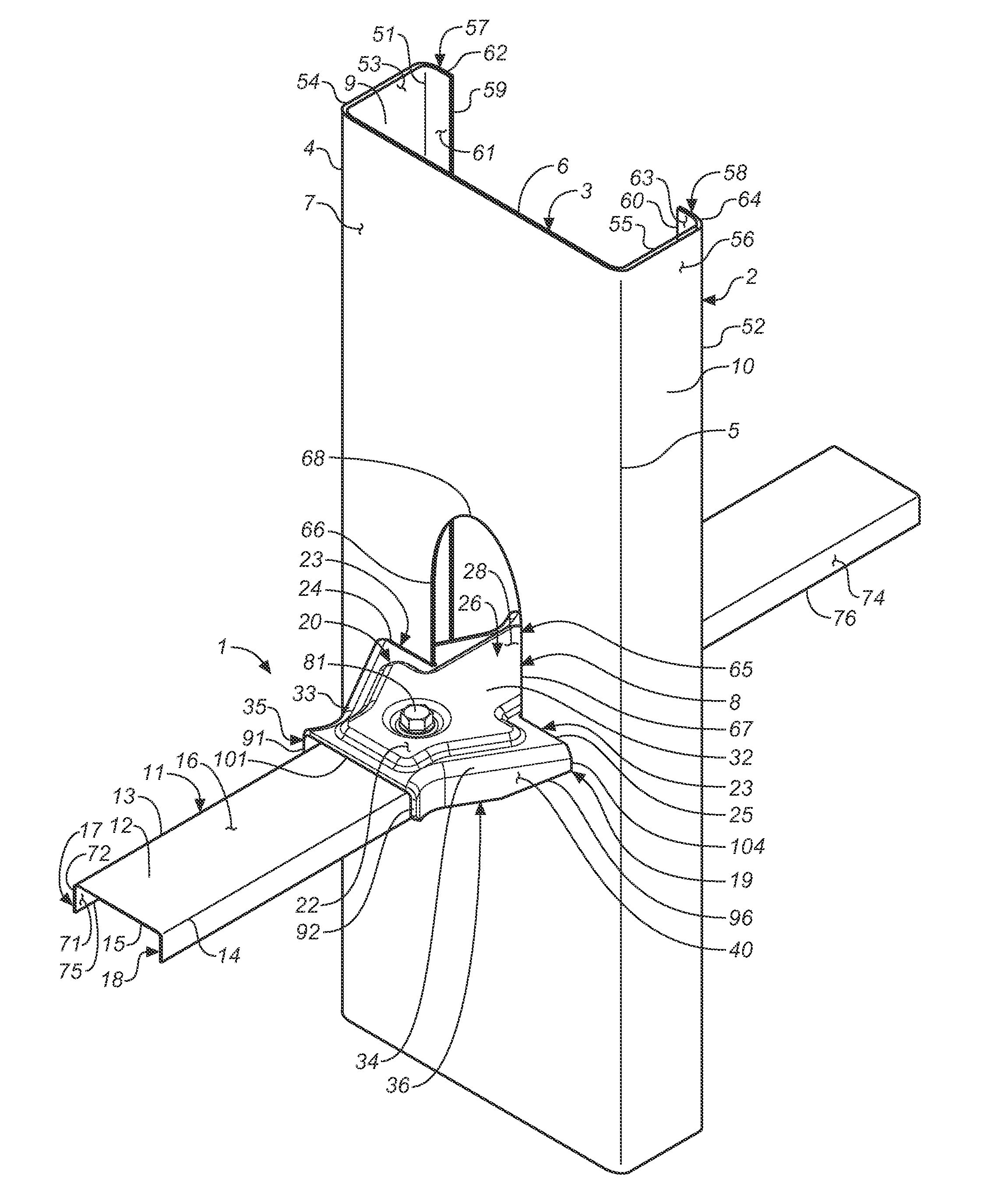
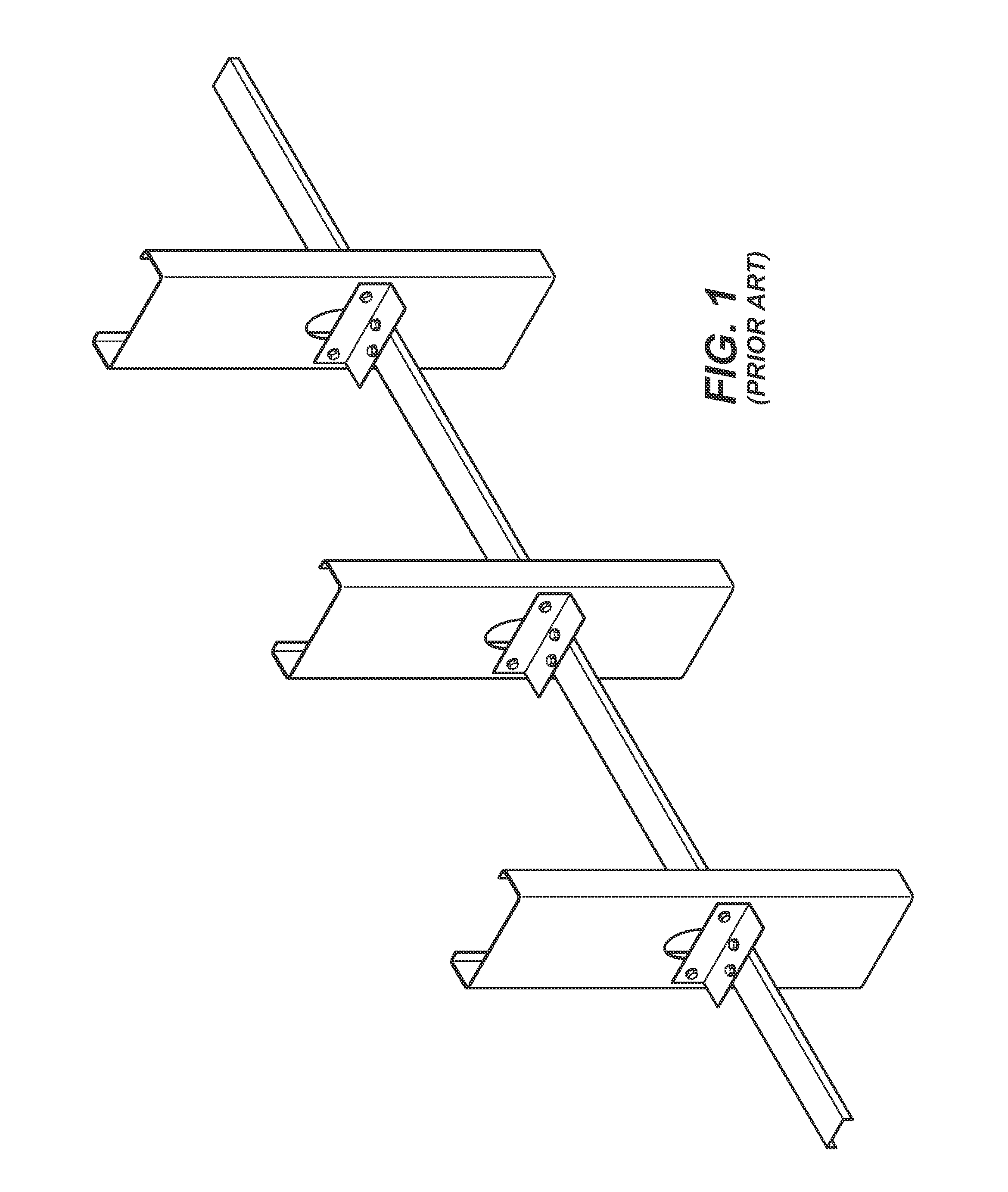
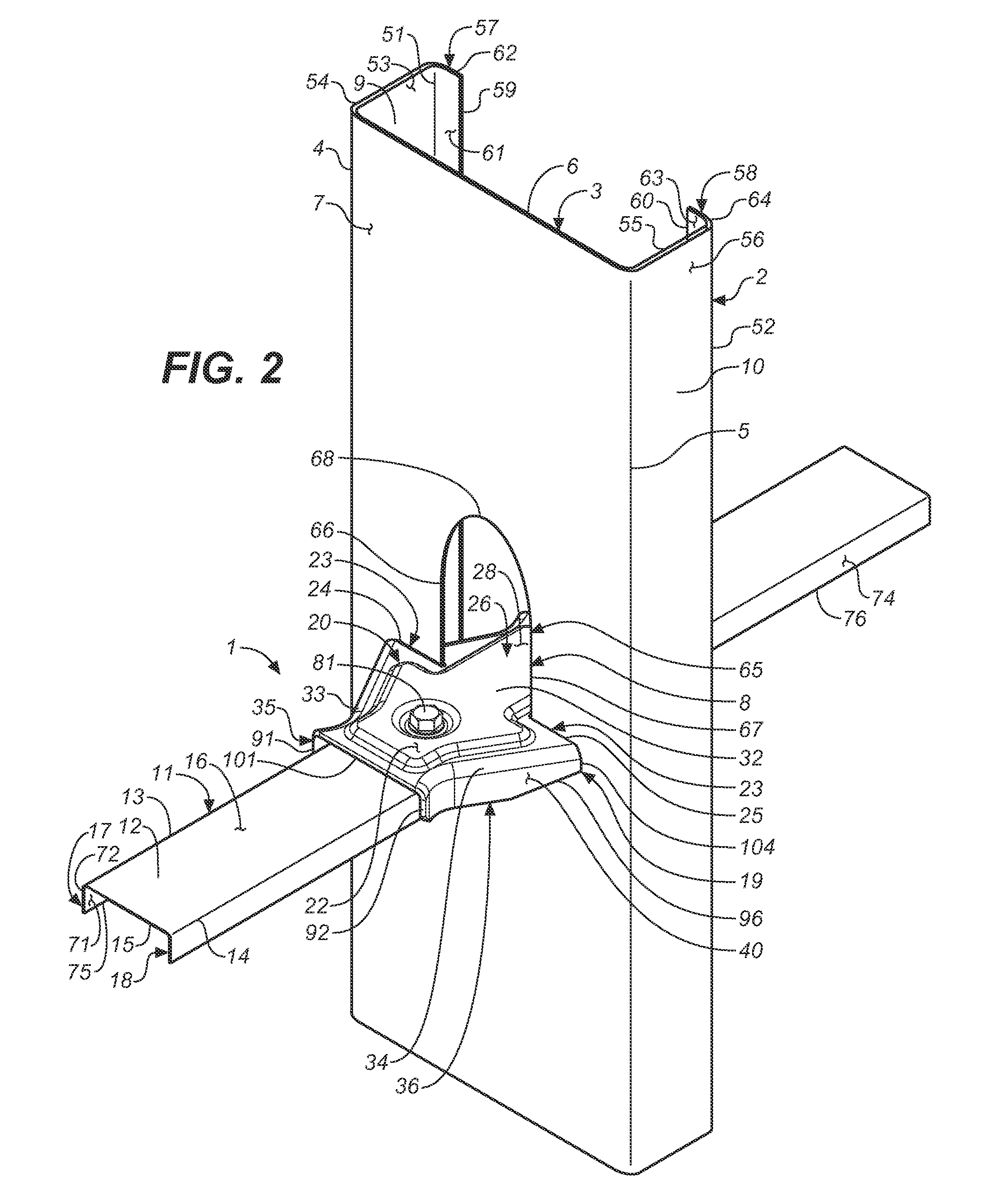
[0037]As shown in FIGS. 2, 4A, 4B, 12 and 16, the present invention is a building connection 1 that comprises a substantially vertical wall stud 2, a substantially horizontal bridging member 11, and a separate, distinct bridging connector 19 that attaches the wall stud 2 to the bridging member 11. The wall stud 2 is typically one of several sequentially-arranged, cold-formed steel studs 2 in the frame of a building wall. The bridging member 11 is typically a separate cold-formed steel member that interfaces with and spans a plurality of wall studs 2. A prior art connection is shown in FIG. 1.

[0038]Typically, the wall stud 2 includes a central web 3 having a first side 4 and a second side 5, an inner surface 6 and an outer surface 7, and a elongated opening 8. The central web 3 is typically rectangular and occupies a vertical plane. A first side flange 9 is integrally attached to the first side 4. A second side flange 10 is integrally attached to the second side 5. The first and seco...


PUM


Abstract

A building connection between a substantially vertical wall stud and a substantially horizontal bridging member, using a separate and distinct bridging connector that attaches the wall stud to the bridging member. The wall stud is typically one of several sequentially-arranged, cold-formed steel studs in the frame of a building wall. The bridging member is typically a separate cold-formed steel member that interfaces with and spans a plurality of wall studs.

Description

BACKGROUND OF THE INVENTION[0001]The present invention relates to steel stud building wall systems and especially to apparatuses for stabilizing steed studs to prevent lateral movement and torsion in such systems.[0002]Many industrial, and a growing number of residential, buildings are constructed with steel stud wall framing for a variety of reasons. Steel framing is fireproof, does not warp, cannot be infested, and does not rot. When a wall is built with any kind of stud, wood or steel, it is generally desirable to fix sequential studs relative to each other and each against lateral movement and torsion. In wood-stud walls, a short piece of wood blocking is typically nailed to adjacent stud pairs to stabilize them. In steel-stud walls, an elongated steel bridging member is typically inserted horizontally through pre-punched openings in a series of vertical studs to keep them aligned. Steel studs have excellent columnar strength when they are straight, but a significant portion of ...

Claims


Application Information

Patent Timeline
Patent Type & Authority Applications(United States)
IPC IPC(8): E04G25/00E04B1/38E04C3/07
CPCE04C3/07E04C2003/0473E04B1/1903E04B2/763
Inventor DAUDET, LARRY RANDALLLIN, JIN-JIE
Owner SIMPSON STRONG TIE
Why Eureka
Try Eureka