Collapsible easel

a technology of easels and beams, applied in the field of collapsible easels, can solve the problems of reducing the overall length of the main beam

Active Publication Date: 2013-05-02
PANNO JR NICHOLAS J
View PDF5 Cites 2 Cited by
  • Summary
  • Abstract
  • Description
  • Claims
  • Application Information

AI Technical Summary

Benefits of technology

[0016]Some embodiments comprise a main beam having a first end and a second end spaced apart from the first end, the main beam defining a length, wherein the main beam comprises a receiving member and a slide member, the receiving member defining, and at least partially enclosing, a slide retaining space adapted to receive the slide member in a slidable retaining relation, wherein the slide member can retract into the slide retaining space reducing the overall length of the main beam, and the slide member can extend out of the slide retaining space increasing the overall length of the main beam; a first support attached to an end of the main beam, the first support defining a first retaining trough, the first retaining trough running at least part of a length of the first support, and the first retaining trough being bounded at least by a portion of a face of the first support and a portion of a face of the main beam, wherein the first retaining trough is adapted to receive a work piece defined by an artist's canvas in a retaining relation, and wherein the first support comprises a pair of supports each defining an inner end and an outer end, the pair of supports each being hingedly attached through their inner ends to the main beam at opposing sides of the main beam; a second support attached to an end of the main beam opposing the end to which the first support is attached, the second support defining a second retaining trough, the second retaining trough running at least part of a length of the second support and the second retaining trough being bounded by at least a portion of a face of the second support and a portion of a face of the main beam, the shortest distance between the face of the second support and the face of the main beam defining a width of the second retaining trough, wherein the width of the second retaining trough is adjustable according to a width adjustment means, wherein the second retaining member is adapted to receive a work piece defined by an artist's canvas in a compressive retaining relation, and wherein the second support comprises a pair of supports each defining an inner end and an outer end, the pair of supports each being hingedly attached through their inner ends to the main beam at opposing sides of the main beam; and a base fixedly attached to an end of the main beam, the base having a first face in contact with the main beam and through which the base is attached to the main beam, and the base having a second face spaced apart from, and generally parallel to, the first face, wherein the second face further includes a means for receiving a stand in a supportive relation.
[0017]Some embodiments further comprise a means for fixing the position of the slide member relative to the receiving member, thereby fixing the overall length of the main beam.

Problems solved by technology

However, these devices, while adjustable, retain their relative size and shape.
Although this may be inconsequential while painting in an art studio, it is problematic during travel.
Not only is the easel large and cumbersome, but often space is limited.

Method used


Image

  • Collapsible easel
  • Collapsible easel
  • Collapsible easel

Examples


embodiment 100

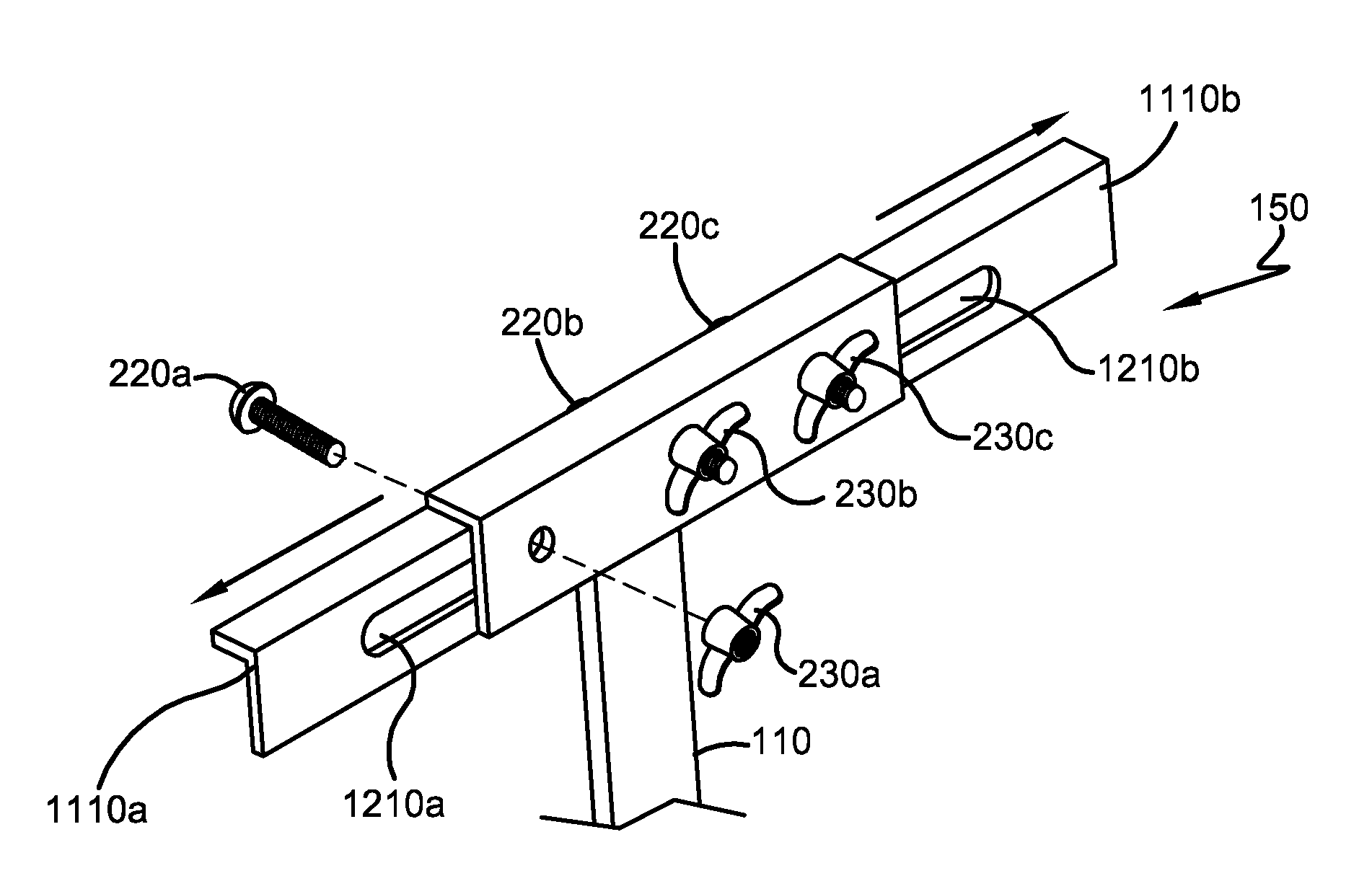
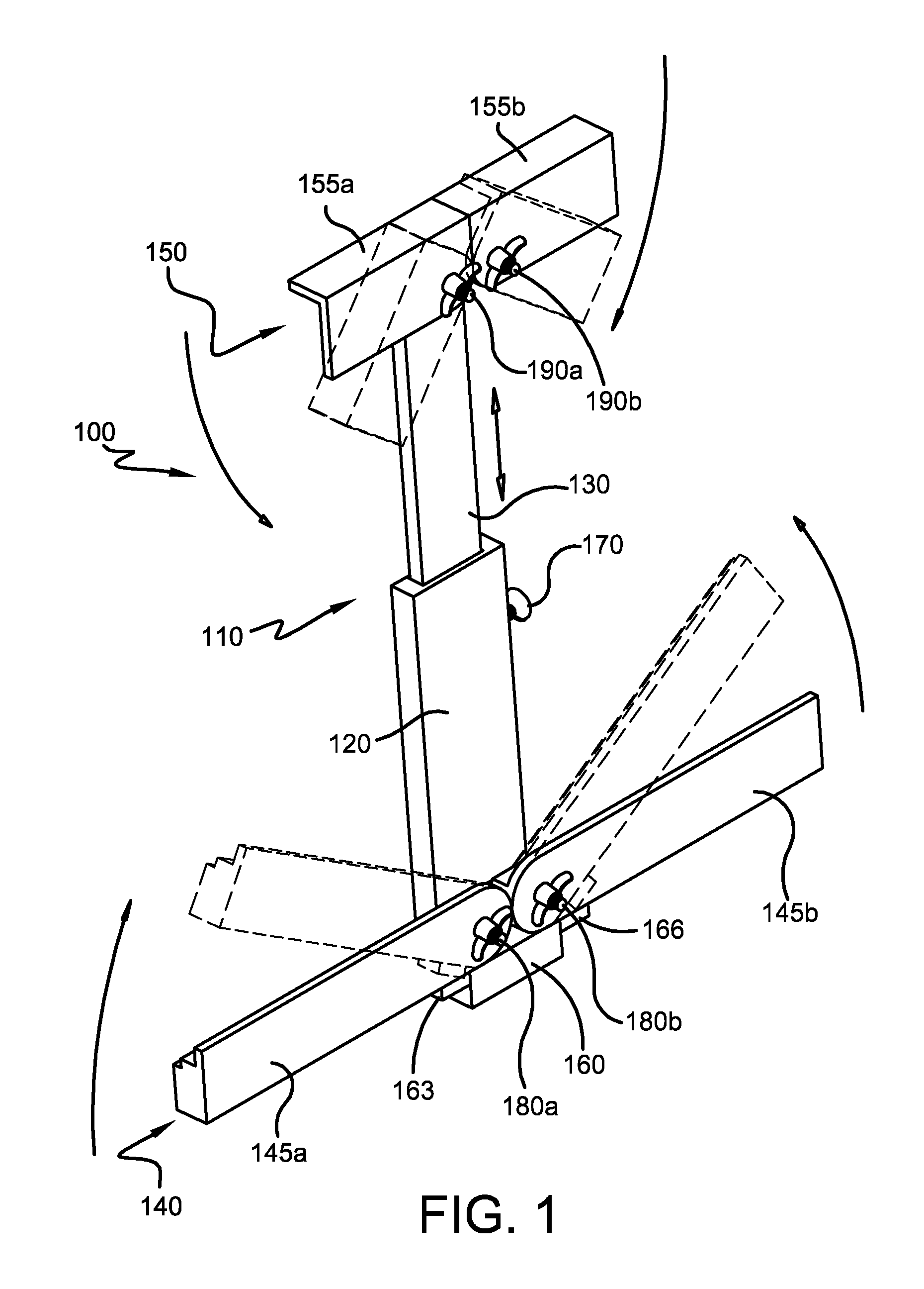
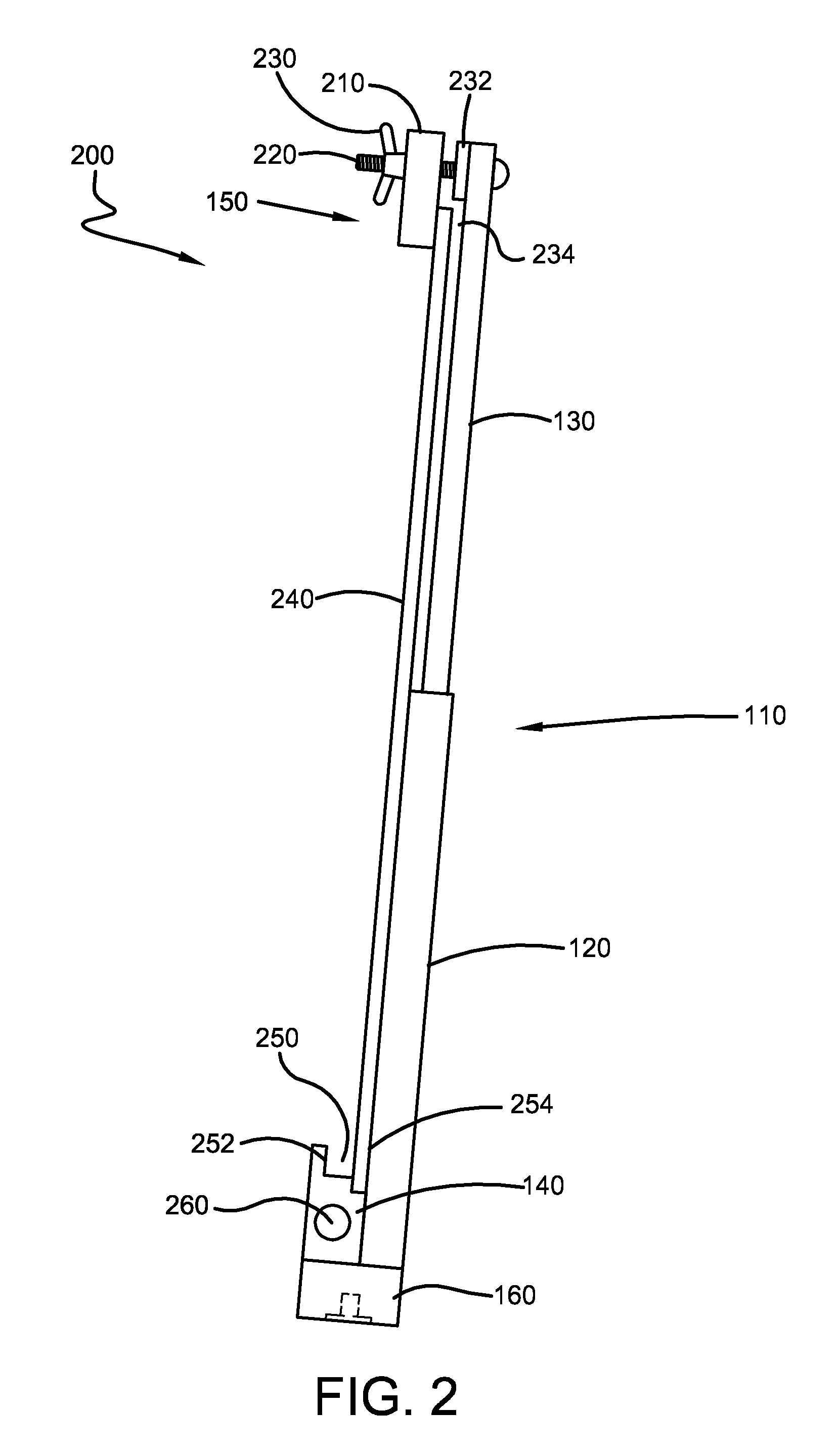
[0045]Referring now to the drawings wherein the showings are for purposes of illustrating embodiments of the invention only and not for purposes of limiting the same, FIG. 1 is a drawing of an embodiment 100 having a main beam 110 comprising a receiving member 120 receiving a slide member 130 in a slidable relation. The embodiment of FIG. 1 also includes a first support 140 comprising a pair of supports 145a, 145b in a mirrored relation, each of which is hingedly fastened to the receiving member 120 at one end of the supports 145a, 145b. As further shown in FIG. 1, an embodiment can include a second support 150 comprising a pair of supports 155a, 155b in a mirrored relation, each of which is hingedly fastened to the slide member at one end. The embodiment of FIG. 1 further includes a base 160 fixedly attached to one end of the receiving member 120 and adapted to receive a tripod in a supportive relation. The main beam 110 can be lengthened by extending the slide member 130 outwardly...

embodiment 300

[0048]FIG. 3 is a frontal view of an embodiment 300 in a collapsed configuration. In the embodiment shown in FIG. 3, the pair of supports 145a, 145b comprising the first support 140 are each rotatable through approximately 90 degrees on hinges 180a, 180b towards the main beam 110. Likewise, the pair of supports 155a, 155b comprising the second support 150 are each rotatable through approximately 90 degrees on hinges 190a, 190b towards the main beam 110.

[0049]FIG. 4 is a view 400 of a base 160 of embodiment 300 in a collapsed configuration. In this view 400, a means for receiving a stand 410, such as without limitation a tripod, is disposed in a surface 402 of the base 160. The surface 402 opposes the surface of the base which is affixed to the main beam 110. In some embodiments, the means for receiving a stand 160 comprises a threaded mount. In some alternative embodiments the receiving means 160 can comprise any of a variety of suitable structures known to those of skill in the art...

embodiment 900

[0053]FIG. 9A and FIG. 9B illustrate and embodiment 900 having double hinge elements 912, 914. According to FIG. 9A a first support 140 is hingedly joined to a receiving member 120 through a first double hinge 912. Similarly, a second support 150 is hingedly joined to a slide member 130 through a second double hinge 914. FIG. 9B is an exploded view of a generic support having a double hinge. According to FIG. 9B, a double hinge comprises a recess at one end of a first support 922a defining a curved sidewall 940a allowing for the rotation of the nose 930b of a mating support 922b. The first support 922a further includes a first rotational face 942a adapted to mate with the second rotational face 942b of the second support 922b in a slidable relation adapted to rotate about a bolt 220 which is fastened with a wing nut 230. The bolt 220 is received by apertures 920a, 920b defined in the respective first and second supports 922a, 922b.

[0054]FIG. 10 is a partial view of an embodiment wi...


PUM


Abstract

Some embodiments generally relate to portable easel devices for supporting and/or displaying objects such as canvas, other paintable substrates, or even sheet music. Embodiments may include one or more collapsible elements rendering the device readily storable and/or easier to carry or transport.

Description

I. BACKGROUND OF THE INVENTION[0001]A. Field of Invention[0002]Some embodiments may generally relate to artistic support and / or display devices and methods.[0003]B. Description of the Related Art[0004]Currently, the field of artist easels includes various devices having support elements for securing canvases and the like. However, these devices, while adjustable, retain their relative size and shape. Although this may be inconsequential while painting in an art studio, it is problematic during travel. Not only is the easel large and cumbersome, but often space is limited. Accordingly, there is a need in the art for an easel that can readily and conveniently travel with the artist.[0005]Some embodiments of the present invention may provide one or more advantages over the prior art.II. SUMMARY OF THE INVENTION[0006]Some embodiments may include an easel, comprising a main beam having a first end and a second end spaced apart from the first end and defining a length; a first support att...

Claims


Application Information

Patent Timeline
Patent Type & Authority Applications(United States)
IPC IPC(8): A47B97/04A47B97/08A47B97/00
CPCA47B97/08
Inventor PANNO, JR., NICHOLAS J.
Owner PANNO JR NICHOLAS J
Why Eureka
Try Eureka