
Reactor and manufaturing method thereof

a technology of manufaturing method and reactor, which is applied in the direction of transformer/inductance details, electrical apparatus, transformer/inductance magnetic core, etc., can solve the problems of increasing the complexity of a manufacturing process, affecting the accuracy of positioning the plurality of core materials and the spacer in the die, etc., to achieve a high degree of precision and easy positioning in the di

Active Publication Date: 2013-05-02
TAMURA KK
View PDF10 Cites 31 Cited by
  • Summary
  • Abstract
  • Description
  • Claims
  • Application Information

AI Technical Summary

Benefits of technology

The present invention is aimed at providing a reactor and manufacturing method that makes it easy to position a core material in a die and accurately place multiple core materials and a spacer within molded resin. This allows for the production of molded cores that have minimal positional deviation between the core materials.

Problems solved by technology

However, it is difficult to position the plurality of core materials and the spacer in the die accurately, and therefore positional deviation may occur between the core materials.
With this method, however, a process for adhering the core materials to the spacer must be performed, leading to an increase in the complexity of a manufacturing process.
Hence, with the prior art, it is difficult to position the core materials and the spacer accurately in the molded core, and as a result, problems occur in that the molded core cannot be manufactured easily and the manufactured molded core is not able to exhibit an intended performance.

Method used


Image

  • Reactor and manufaturing method thereof
  • Reactor and manufaturing method thereof
  • Reactor and manufaturing method thereof

Examples


first embodiment

1. First Embodiment

Configuration

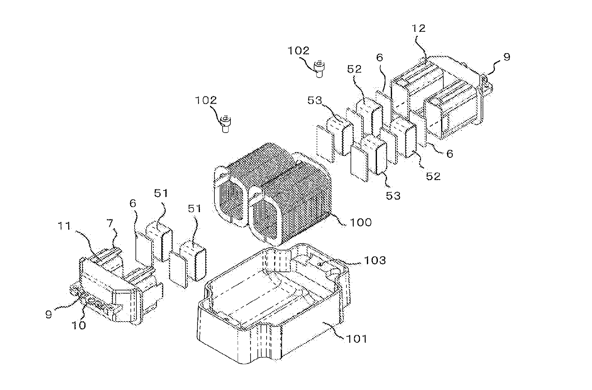
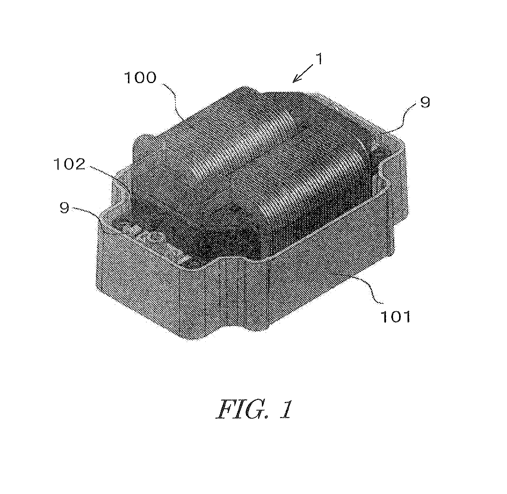
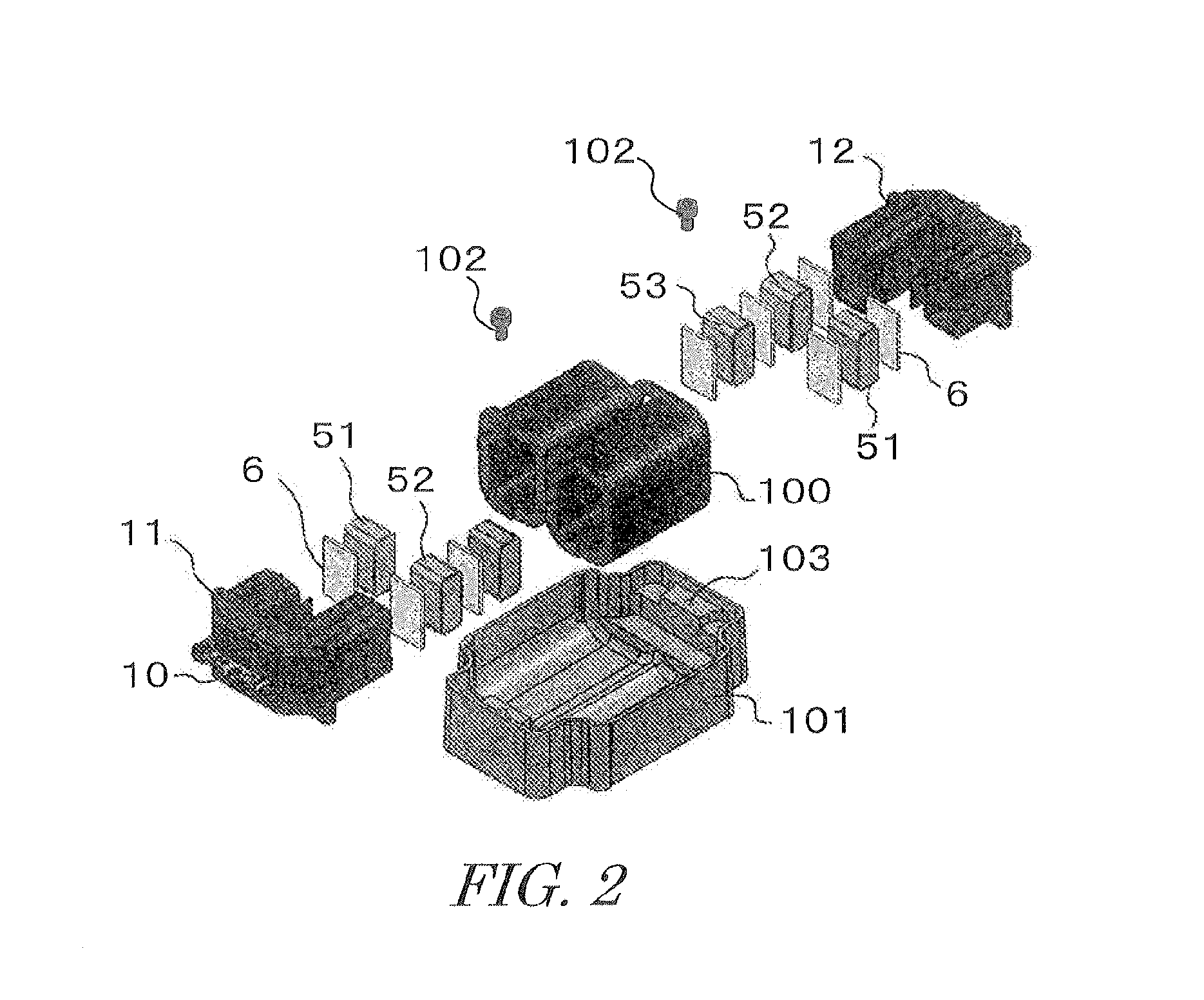
[0028]As shown in FIGS. 1 and 2, a reactor according to this embodiment is constituted by a molded core 1, a coil 100 wound around the molded core 1, and a case 101 housing the molded core 1 and the coil 100. The molded core 1 is formed in a ring shape by abutting and integrating two J-shaped divided cores 11, 12. More specifically, the divided cores 11, 12 are vertically symmetrical members, and the ring-shaped molded core 1 can be manufactured by inverting one divided core 12 upside-down and then combining the inverted divided core 12 with the other, non-inverted divided core 11.

[0029]The respective divided cores 11, 12 are constituted by left and right leg portions 11a, 12a and yoke portions 11b, 12b connecting the leg portions 11a, 12a, and are formed by molding a U-shaped yoke portion side core material 2 within resin 3, as shown in FIG. 5. Left and right end surfaces 2a of the yoke portion side core material 2 molded within the resin 3 are expos...

second embodiment

2. Second Embodiment

[0045]FIGS. 6 to 9 show a second embodiment of the present invention. In this embodiment, the two divided cores 11, 12 are both formed in a U shape. More specifically, in this embodiment, a length of left and right core mounting portions 41 of the first divided core 11 is set such that one leg portion side core material 51 can be mounted in the interior thereof, while a length of left and right mounting portions 42 of the second divided core 12 is set such that two leg portion side core materials 52, 53 can be mounted in the interior thereof.

[0046]Three tongue pieces 7 projecting to the second divided core 12 side are provided on respective tip ends of the left and right core mounting portions 41 of the first divided core 11. Three recessed portions 8 into which the tongue pieces 7 on the first divided core fit are provided on respective tip ends of the left and right core mounting portions 42 of the second divided core 12.

[0047]Other configurations and a manufac...


PUM

PropertyMeasurementUnit
inductanceaaaaaaaaaa
earthquake resistanceaaaaaaaaaa
climate resistanceaaaaaaaaaa

Abstract

Divided cores 11, 12 includes left and right leg portions and a yoke portion and formed by molding a yoke portion side core material within resin. The leg portions of the divided core are formed by tubular core mounting portions 41, 42. I-shaped leg portion side core materials 51-53 and spacers 6 are mounted in the tubular core mounting portions. A ring-shaped molded core 1 is formed by abutting and integrating the respective leg portions of two divided cores, and a coil 100 is wound around the molded core.

Description

FIELD OF THE INVENTION[0001]The present invention relates to a reactor used for example in a vehicle such as an electric automobile or a hybrid vehicle, and a manufacturing method thereof.DESCRIPTION OF THE RELATED ART[0002]In a known conventional reactor installed in a vehicle, a magnetic gap having a predetermined width is provided between a plurality of core materials with the aim of preventing a reduction in inductance. In this type of reactor, an integrated core formed by sandwiching a spacer made of a ceramic or the like in the gap part between the core materials and adhering the spacer to the adjacent core materials using an adhesive is employed.[0003]The reactor is constructed by winding a coil around the core thus formed. In this case, insulation is provided between the core and the coil using a resin bobbin or a molded core in which the entire core is molded from resin. In consideration of earthquake resistance and climate resistance, a molded core is used particularly oft...

Claims


Application Information

Patent Timeline
Patent Type & Authority Applications(United States)
IPC IPC(8): H01F27/26B29C70/68
CPCB29C70/68H01F27/266H01F27/324H01F27/306H01F27/263
Inventor SUZUKI, KOTAROMAENO, KENSUKENAKATSU, RYO
Owner TAMURA KK
Learn More