Methods for adjusting a relative navigation system

a navigation system and relative technology, applied in the field of methods for adjusting a relative navigation system, can solve the problems of limiting reducing the use of the uav, and reducing the flexibility of the uav, so as to achieve the effect of reducing the number of landing aids

Active Publication Date: 2013-05-02
GE AVIATION SYST LLC
View PDF26 Cites 21 Cited by
  • Summary
  • Abstract
  • Description
  • Claims
  • Application Information

AI Technical Summary

Problems solved by technology

UAVs have become increasingly popular but the logistical complexity of UAV control makes their use burdensome.
However, it is often desirable to launch and land UAVs at locations where the infrastructure for traditional landing aids is not available, which limits the flexibility of the UAV.
Additionally, landing aids that emit radio frequency energy have the further disadvantage of being easily targeted.
The landing problem is exacerbated when the UAV is being landed on a moving structure, such as a ship, vehicle, or aircraft, because the existing landing aids are intended to be used on stationary structures and do not compensate for movement of the vehicle or structure on which the UAV is landing.

Method used


Image

  • Methods for adjusting a relative navigation system
  • Methods for adjusting a relative navigation system
  • Methods for adjusting a relative navigation system

Examples


Embodiment Construction

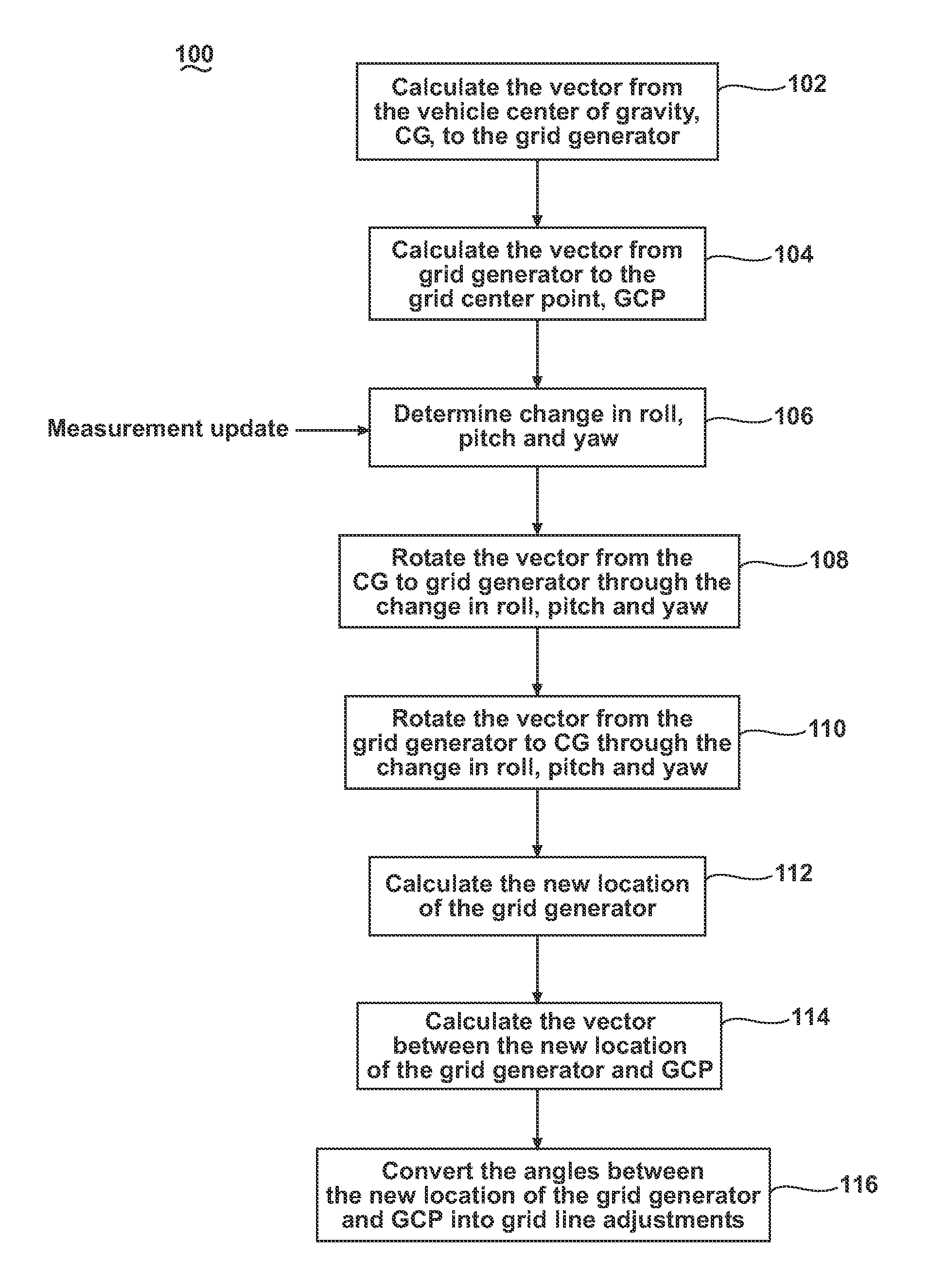
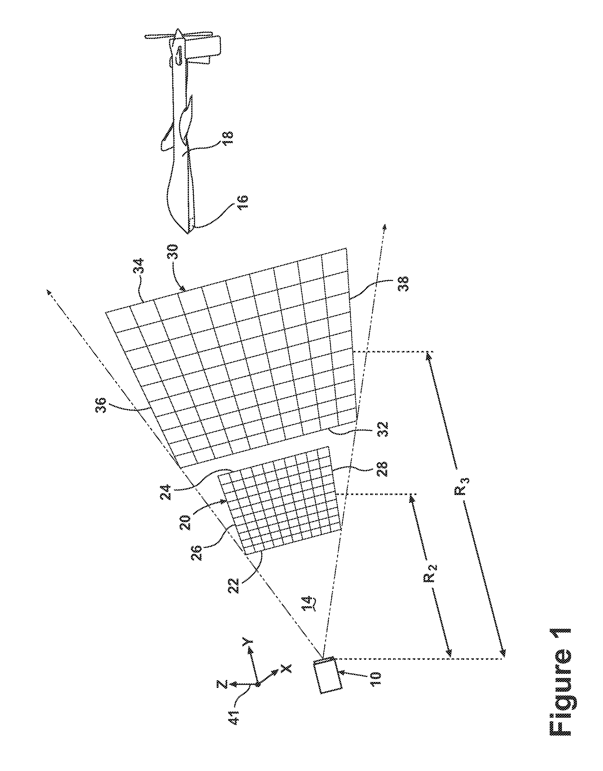
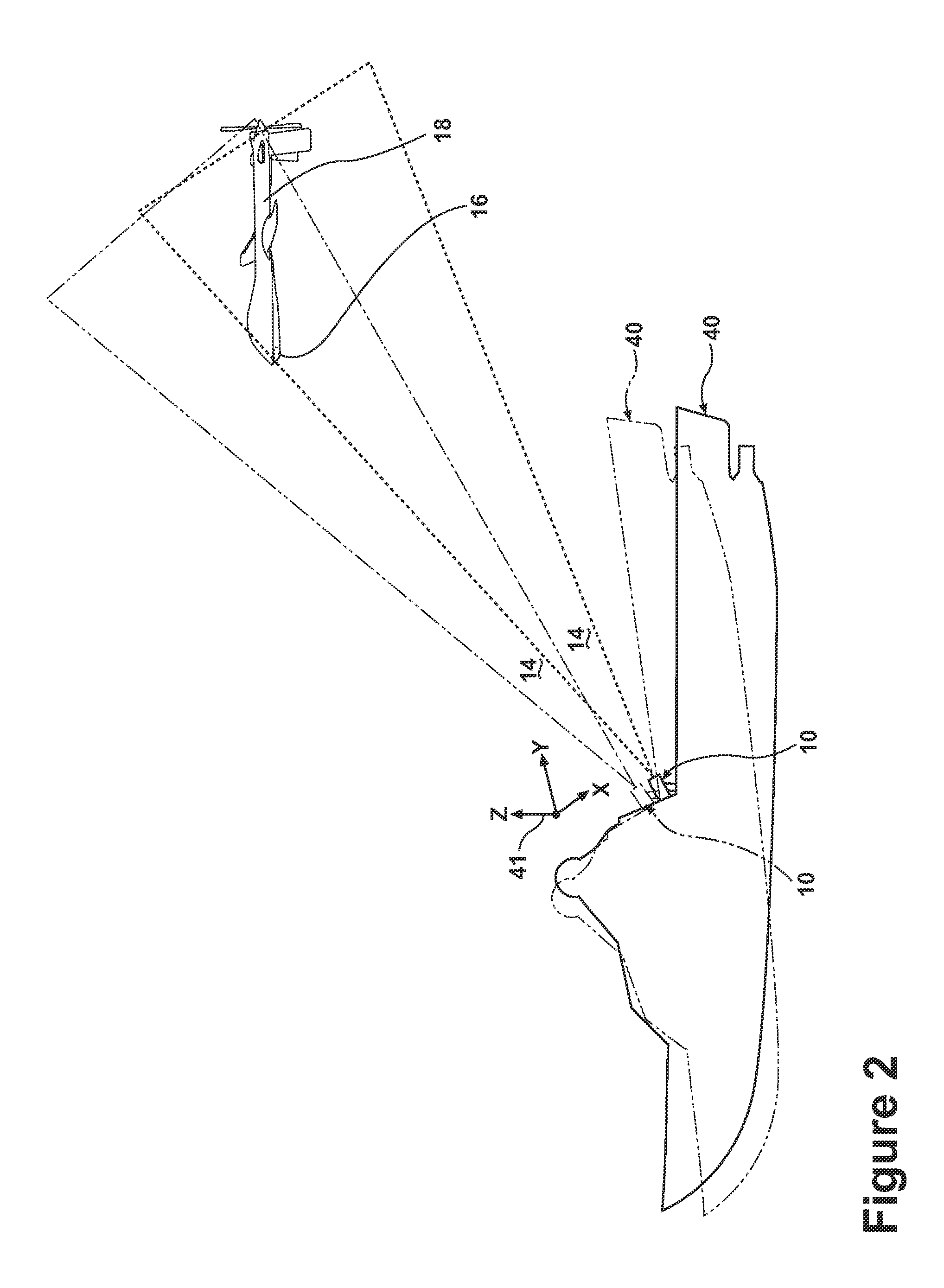
[0012]The embodiments of the present invention are related to methods and apparatus for adjusting a projected grid from a grid generator of a relative navigation system, which may be used for landing any type of aircraft and is particularly well suited for landing UAVs. FIG. 1 illustrates an embodiment of a grid generator 10 may project a grid 12, such as a plurality of intersecting lines, into space within a field of transmission 14. The general details of how to project the grid 12 are known in the art, which include the disclosure in U.S. Pat. No. 7,681,839, issued Mar. 23, 2010, entitled Optical Tracking System For Refueling, and US 2011 / 0153205, published Jun. 23, 2011, entitled Relative Navigation System, both of which are incorporated by reference. Therefore, the general details of the grid generation will not be fully described in this application.

[0013]As illustrated, the projected grid comprises intersecting lines. At some distance away from the grid generator 10, these in...


PUM


Abstract

A relative navigation system projects a grid into space from a grid generator and an object, such as an unmanned aerial vehicle, may use the projected grid to aid in the landing of the object. Methods of adjusting the projected grid including stabilizing the projected grid and orienting the grid generator relative to the earth.

Description

BACKGROUND OF THE INVENTION[0001]Unmanned aerial vehicles (UAVs) are aircraft that fly without onboard pilots. They rely on complete or partial automation for control during their takeoff, flight, and landing. UAVs have become increasingly popular but the logistical complexity of UAV control makes their use burdensome. UAV landings are typically done at locations having traditional landing aids such as Instrument Landing Systems (ILS), Very High Frequency Omnibearing Receivers (VOR), Distance Measuring Equipment (DME) Microware Landing Systems (MLS), RADAR, etc., which aid the remote pilot in landing the aircraft and / or provide for automated landings. However, it is often desirable to launch and land UAVs at locations where the infrastructure for traditional landing aids is not available, which limits the flexibility of the UAV. Additionally, landing aids that emit radio frequency energy have the further disadvantage of being easily targeted. The landing problem is exacerbated when ...

Claims


Application Information

Patent Timeline
Patent Type & Authority Applications(United States)
IPC IPC(8): G03B21/00
CPCG01C21/24G08G5/025G01S1/70G05D1/0684B64F1/20
Inventor FELDMANN, MICHAEL STEVENSAGGIO, III, FRANKWASHBURN, JOHN ROBERT
Owner GE AVIATION SYST LLC
Why Eureka
Try Eureka