

Lighting apparatus
- Summary
- Abstract
- Description
- Claims
- Application Information
AI Technical Summary
Benefits of technology
Problems solved by technology
Method used
Image

Examples
first embodiment
[0034]A lighting apparatus according to the present invention will be described in detail in reference to the accompanying drawings as follows. The accompanying drawings are illustrated to describe examples of the present invention and they are provided to explain the present invention more specifically, as the present invention is not limited thereto.
[0035]Reference will now be made in detail to the specific embodiments of the present invention, examples of which are illustrated in the accompanying drawings. Wherever possible, the same reference numbers will be used throughout the drawings to refer to the same or like parts. Repeated description will be omitted and the size and appearance of each part illustrated for explanation convenience may be exaggerated or minimized.
[0036]Meanwhile, terminology including ordinal numbers like ‘first’ and ‘second’ may be used to explain various parts of the present invention and the various parts are not limited by the terminology. The terminol...
second embodiment
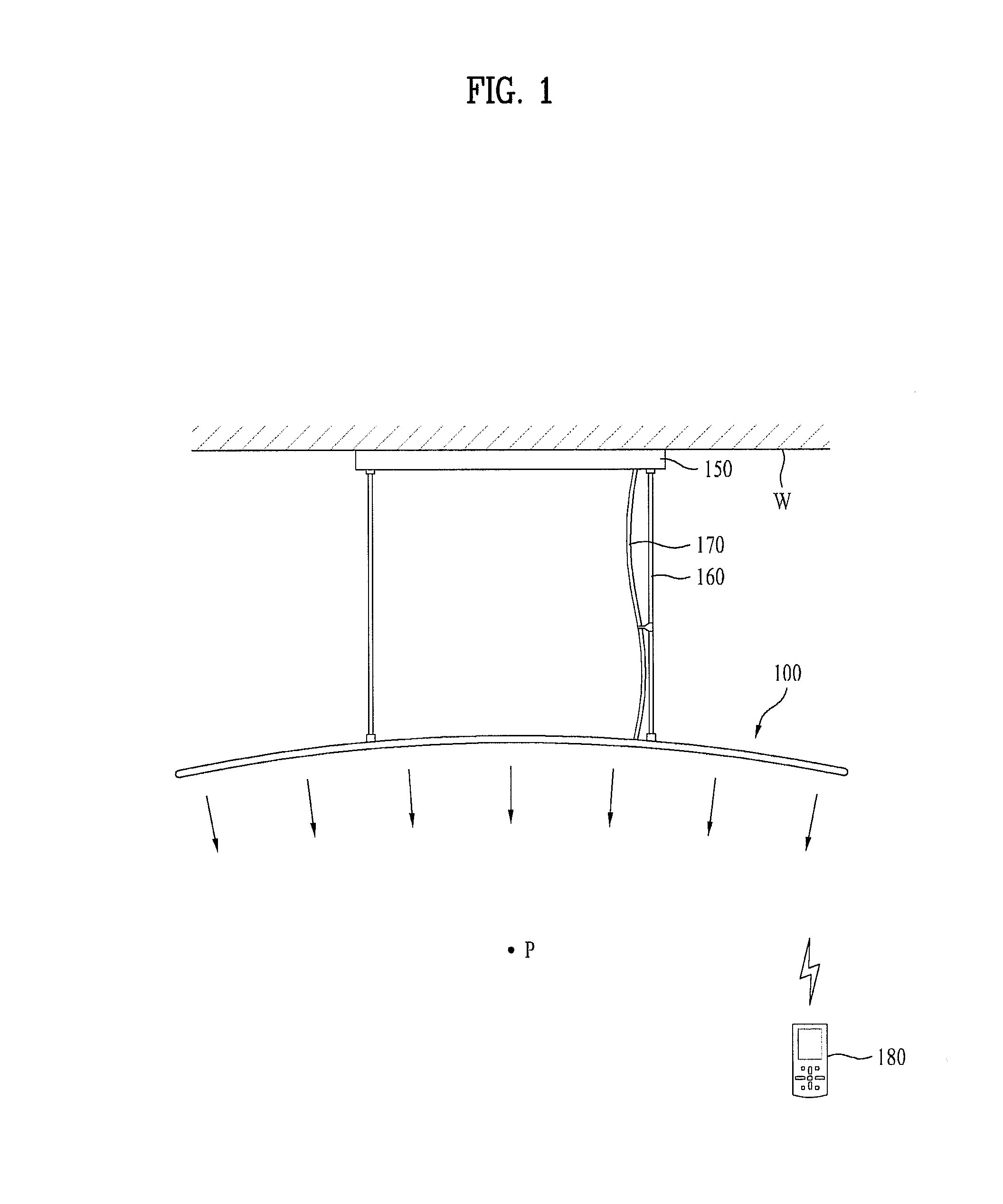
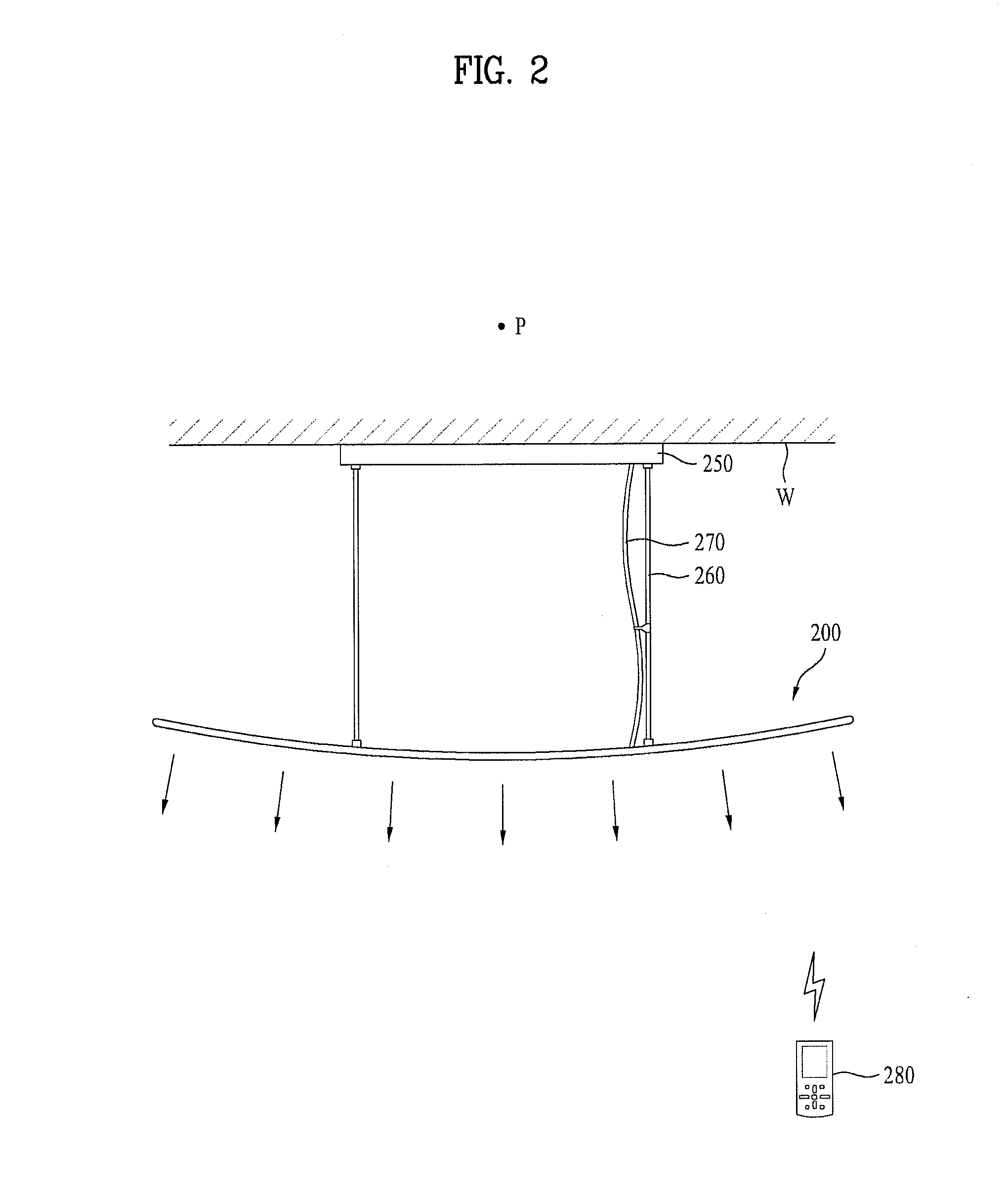
[0070]FIG. 2 is a side view illustrating a lighting apparatus according to the invention.
[0071]The lighting apparatus 200 according to the second embodiment includes a front cover (not shown) having a light transmission part, a rear cover (not shown) coupled to the front cover, a light emitting module including a flexible circuit board 231 arranged between the front cover and the rear cover, with a predetermined curvature having a center positioned toward a reverse direction with respect to a lighting room to increase a light distribution region, and a plurality of LEDs 232 mounted on the flexible circuit board 231, and an electronic module 250 to provide an electric power to the light emitting module.
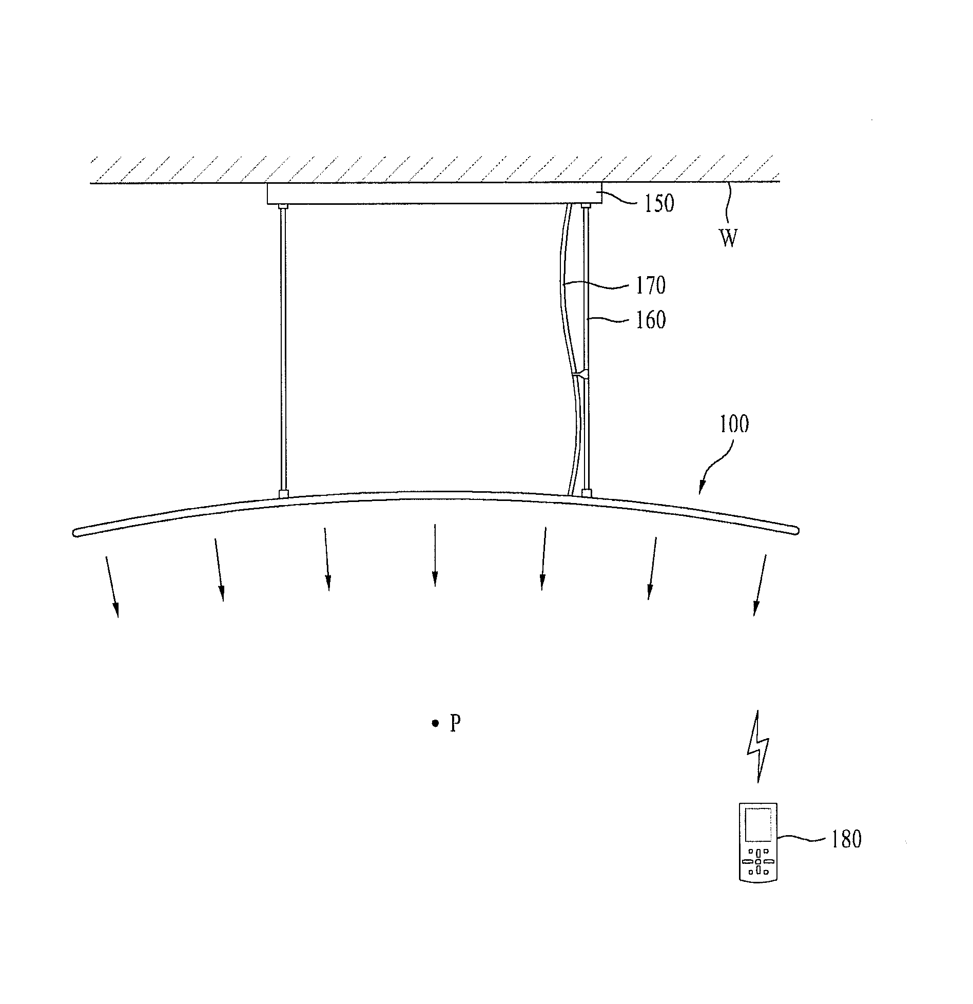
[0072]In reference to FIGS. 1 and 2, the lighting apparatus 200 according to the second embodiment has a different configuration that the light emitting module and the covers are curved along a different direction to locate the center (P) of the curvature in opposite to the center of t...
third embodiment
[0082]FIG. 9 is a conceptual diagram illustrating a lighting apparatus 300 according to the invention.
[0083]The lighting apparatus 300 may include a front cover 310 having a light transmission part, a rear cover 320 coupled to the front cover 310, a light emitting module 330 arranged between the front cover 310 and the rear cover 320, having a flexible circuit board and a plurality of LEDs mounted on the flexible circuit board, a driving unit 360 to bend the flexible circuit board toward a lighting room or a reverse direction with respect to the lighting room, and an electronic module 350 to provide an electric power to the light emitting module 330 and the driving unit 360.
[0084]In the lighting apparatus 100 according to the first embodiment and the lighting apparatus 200 according to the second embodiment, the flexible circuit board has the predetermined curvature fitted to the characteristics of the lighting room. However, in the lighting apparatus 100 according to the third embo...
PUM
| Property | Measurement | Unit |
|---|---|---|
| Angle | aaaaa | aaaaa |
| Flexibility | aaaaa | aaaaa |
| Distance | aaaaa | aaaaa |
Abstract
Description
Claims
Application Information