Method and apparatus for generating a three-dimensional model of a region of interest using an imaging system

a three-dimensional model and imaging system technology, applied in the field of imaging systems, can solve the problems of insufficient information, complex region of interest, and much more expensive tomosynthetic x-ray imaging systems than two-dimensional x-ray imaging systems, and achieve the effects of improving accuracy, robust detection, and increasing precision

Active Publication Date: 2013-05-02
NORDSON CORP
View PDF2 Cites 30 Cited by
  • Summary
  • Abstract
  • Description
  • Claims
  • Application Information

AI Technical Summary

Benefits of technology

[0013]A method in accordance with the first aspect allows for the use of relatively inaccurate, and accordingly inexpensive, positioning mechanisms by correcting for positional inaccuracies during image processing. Typically, the radiation source is stationary and the target object and detector are moved through predetermined positions relative to the source. A method in accordance with the first aspect of the invention uses a fiducial marker of known geometry on or near the region of interest of a target object to adjust captured images of the region of interest and fiducial marker to compensate for inaccuracies in the positioning of the detector and the region of interest relative to the radiation source. In this method, both the region of interest and fiducial marker are moved through predetermined positions. The intended spatial relationship between the radiation source, region of interest (and fiducial marker) and detector at each predetermined position is known. The geometry of the fiducial marker is known (or is assumed to be known). Using this information, together with a known or measured initial position of the fiducial marker, expected images of the fiducial marker can be calculated for each predetermined position of the fiducial marker and detector.
[0016]Thus, the method allows tomosynthesis techniques to be used with existing x-ray imaging machines used for generating two-dimensional images, which do not otherwise have accurate enough mechanical positioning components to produce good quality three-dimensional images. In prior tomosynthesis systems, the position of the detector and target object need to be accurately known to within a fraction of a pixel on the detector, typically within a fraction of a micron. This requires all of the mechanical components in the movement mechanisms to be highly accurately machined to within very tight tolerances. This is a major factor in the cost of tomosynthesis machines. Such tight tolerances are not required with the present invention and accordingly, the method provides users with significant cost savings.
[0022]The fiducial marker may comprise a plurality of fiducial marker elements. For example, the fiducial marker may comprise two, three or more solder balls. The fiducial marker elements may be spaced throughout the region of interest. Arrays of fiducial markers that are arranged to give information throughout the image, or from an area of the image that shows errors typical of the whole image, can provide information for the correction of rotation, scale, keystone distortions or higher order transforms. A single fiducial marker positioned inside the area of interest could be unavoidably obscured by other components inside the area of interest. That could cause imprecision in fiducial detection and subsequently in image transformation. However, having an array of fiducial markers increases precision and makes detection much more robust. It is highly unlikely that all fiducials will be obscured by other components at the same time. Having at least one fiducial without occlusion at time is sufficient for accurate detection.
[0023]The fiducial marker may have a predetermined non-symmetric shape. For example, the fiducial marker may take the form of a star with one arm missing. Non-symmetric shapes may provide more information about rotational errors by providing an absolute index of position, as well as about distortions due to pitch or tilt of the support or detector, than highly symmetric fiducial markers. Such distinctive shapes may also have the advantage of being unambiguously recognisable in each image.
[0024]However, for simple processing, a spherical shaped marker may be used, such as a solder ball. The expected second image of the fiducial marker may then be calculated based on an assumption that the fiducial marker, or each fiducial marker element, has rotational symmetry. This simplifies the required image processing.

Problems solved by technology

This two-dimensional imaging technique is effective but often provides insufficient information.
For example, there may be objects that occlude the desired view through the region of interest or it may simply be that the region of interest is sufficiently complicated to require review in three dimensions.
This need for high precision mechanical equipment makes tomosynthetic x-ray imaging systems much more expensive than two-dimensional x-ray imaging systems.

Method used


Image

  • Method and apparatus for generating a three-dimensional model of a region of interest using an imaging system
  • Method and apparatus for generating a three-dimensional model of a region of interest using an imaging system
  • Method and apparatus for generating a three-dimensional model of a region of interest using an imaging system

Examples


Embodiment Construction

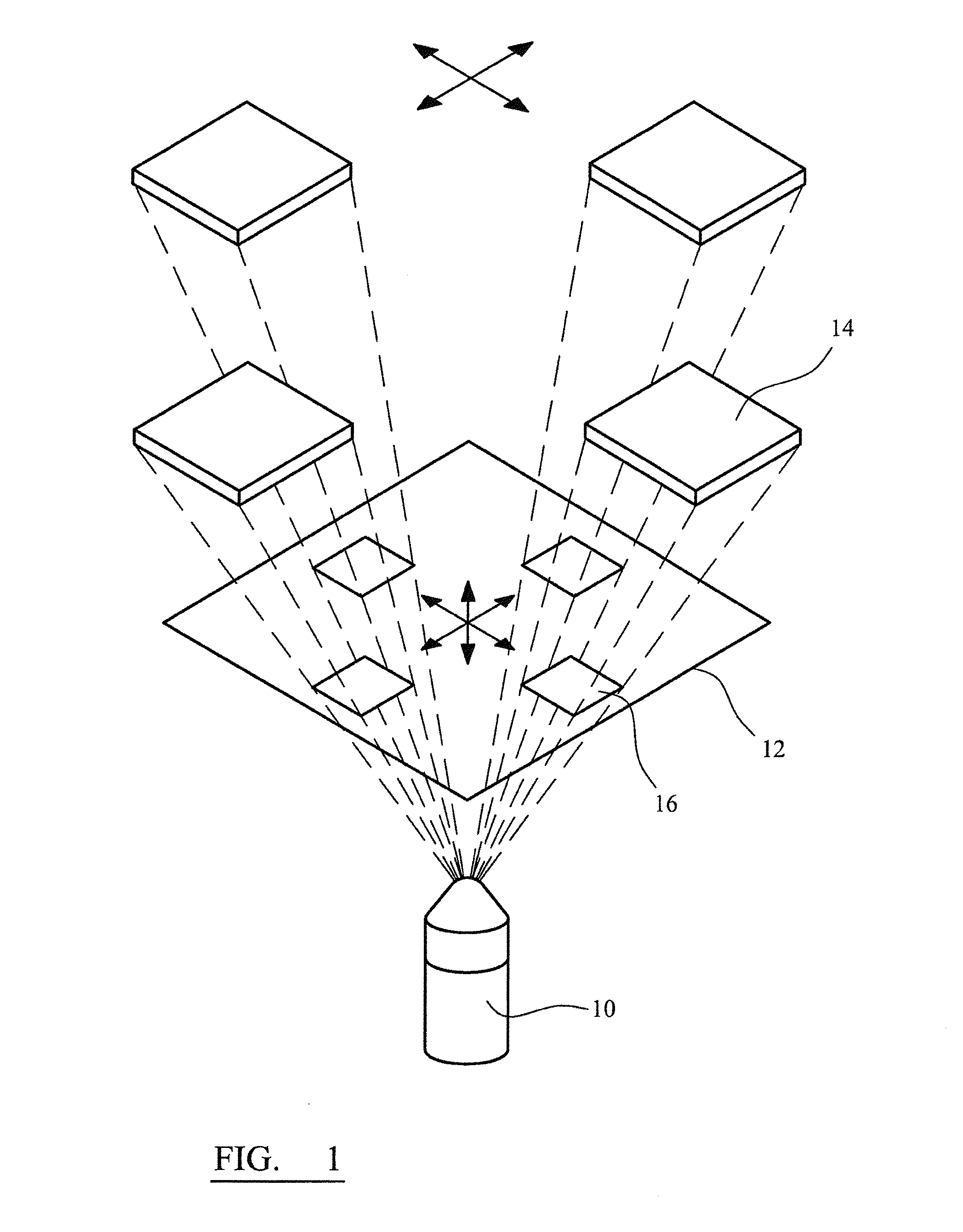
[0052]FIG. 1 is a schematic illustration of the basic elements of an x-ray imaging system. The system shown in FIG. 1 comprises an x-ray source 10, which in this system is held stationary, a moveable support 12 and a moveable detector 14. It is advantageous to keep the x-ray source stationary as it is a relatively bulky and massive component. It also requires very large power cables which are relatively inflexible and difficult to move. X-rays from the x-ray source 10 pass through the support and any target objects mounted on the support, and impinge on the detector 14. FIG. 1 illustrates the areas 16 on the support corresponding to the field of view of the detector 14. The field of view of the detector is selected by a user by the relative positioning of the detector 14, support 12 and x-ray source 10 so that the region of interest of the target object is within the field of view of the detector. The detector can move to different positions so that different projections can be take...


PUM

PropertyMeasurementUnit
diameteraaaaaaaaaa
diameteraaaaaaaaaa
angleaaaaaaaaaa

Abstract

A method of generating a three-dimensional representation of a region of interest on a target object in an x-ray imaging system. The method uses a fiducial marker of known geometry. The region of interest and the fiducial marker are imaged in a plurality of predetermined positions. Expected images of the fiducial marker for each predetermined position are calculated and compared to captured images of the fiducial marker at each predetermined position. The difference between expected and captured imaged is used to generate corrected images of the region of interest for each predetermined position and these corrected images are used to generate a three-dimensional model of the region of interest. The method allows for the generation of useful three-dimensional models of a region of interest in an x-ray imaging system without requiring an expensive mechanical positioning system.

Description

FIELD OF THE INVENTION[0001]The invention relates to an imaging system that is configured to generate a three-dimensional model of a region of interest of a target object using a plurality of two-dimensional images. More particularly, the invention relates to an X-ray imaging system that uses fiducial markers of known geometry to allow a high quality three-dimensional model to be obtained using inexpensive imaging equipment.BACKGROUND TO THE INVENTION[0002]It is necessary to inspect circuit components and their mountings to check for the presence of defects or in order to determine the cause of the defects. One known technique for inspecting the internal structure of integrated circuit components and their mountings onto printed circuit boards is X-ray imaging. X-rays from an X-ray source are passed through a region of interest on a circuit board and the resulting X-ray image or projection is detected by an X-ray detector on the opposite side of the circuit board to the X-ray source...

Claims


Application Information

Patent Timeline
Patent Type & Authority Applications(United States)
IPC IPC(8): G03C9/08
CPCG06T7/0008G06T7/0075G06T11/005G06T2211/436G06T2207/10116G06T2207/30141G06T2207/30204G06T2207/10012G06T7/593G06T17/00G01N23/046
Inventor GOLUBOVIC, DRAGOSTINGAY, JOHN
Owner NORDSON CORP
Why Eureka
Try Eureka