
Solar Grounding Spring

Inactive Publication Date: 2013-05-02
ROTH JEFFREY DAVID
View PDF0 Cites 6 Cited by
  • Summary
  • Abstract
  • Description
  • Claims
  • Application Information

AI Technical Summary

Benefits of technology

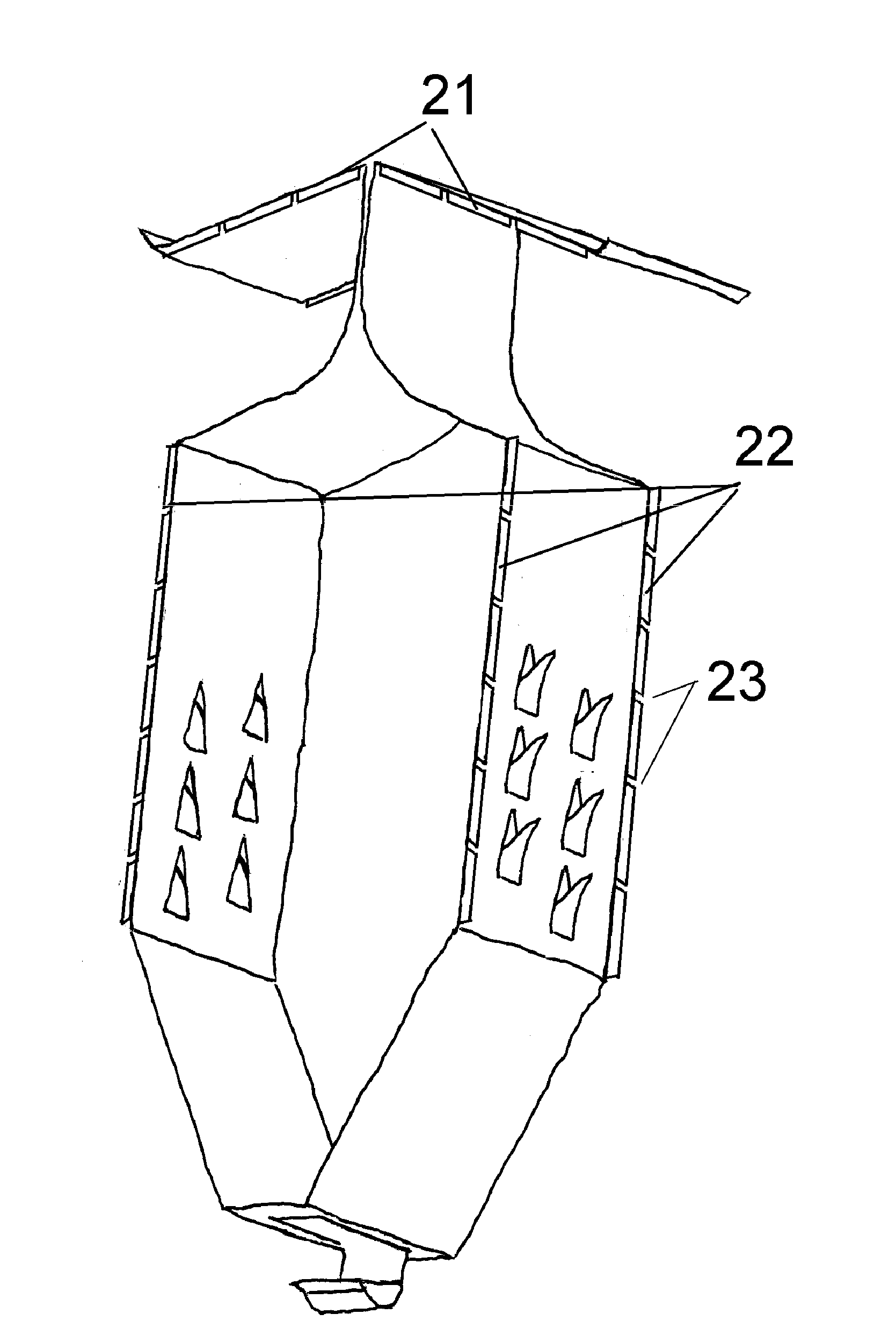
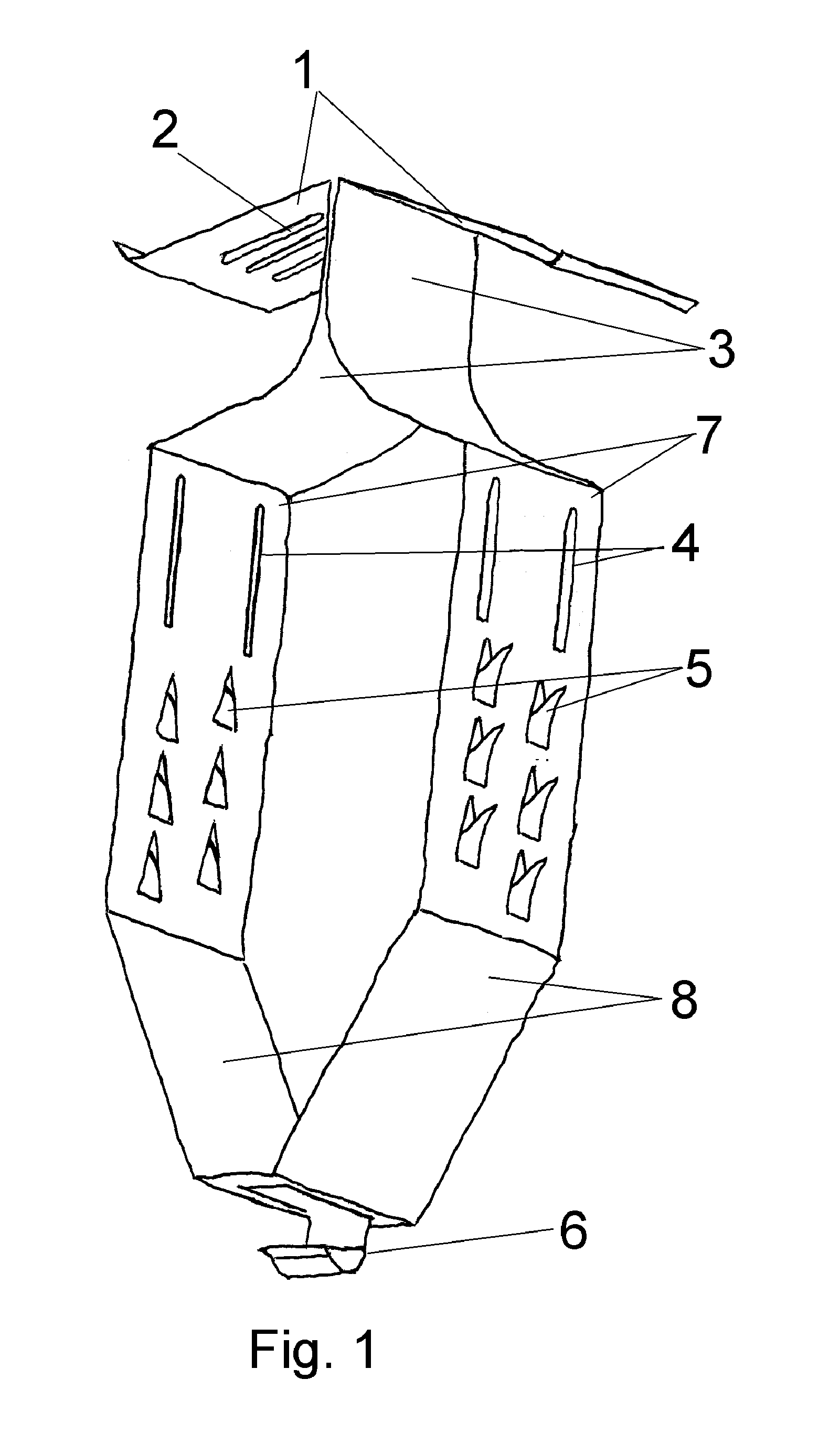
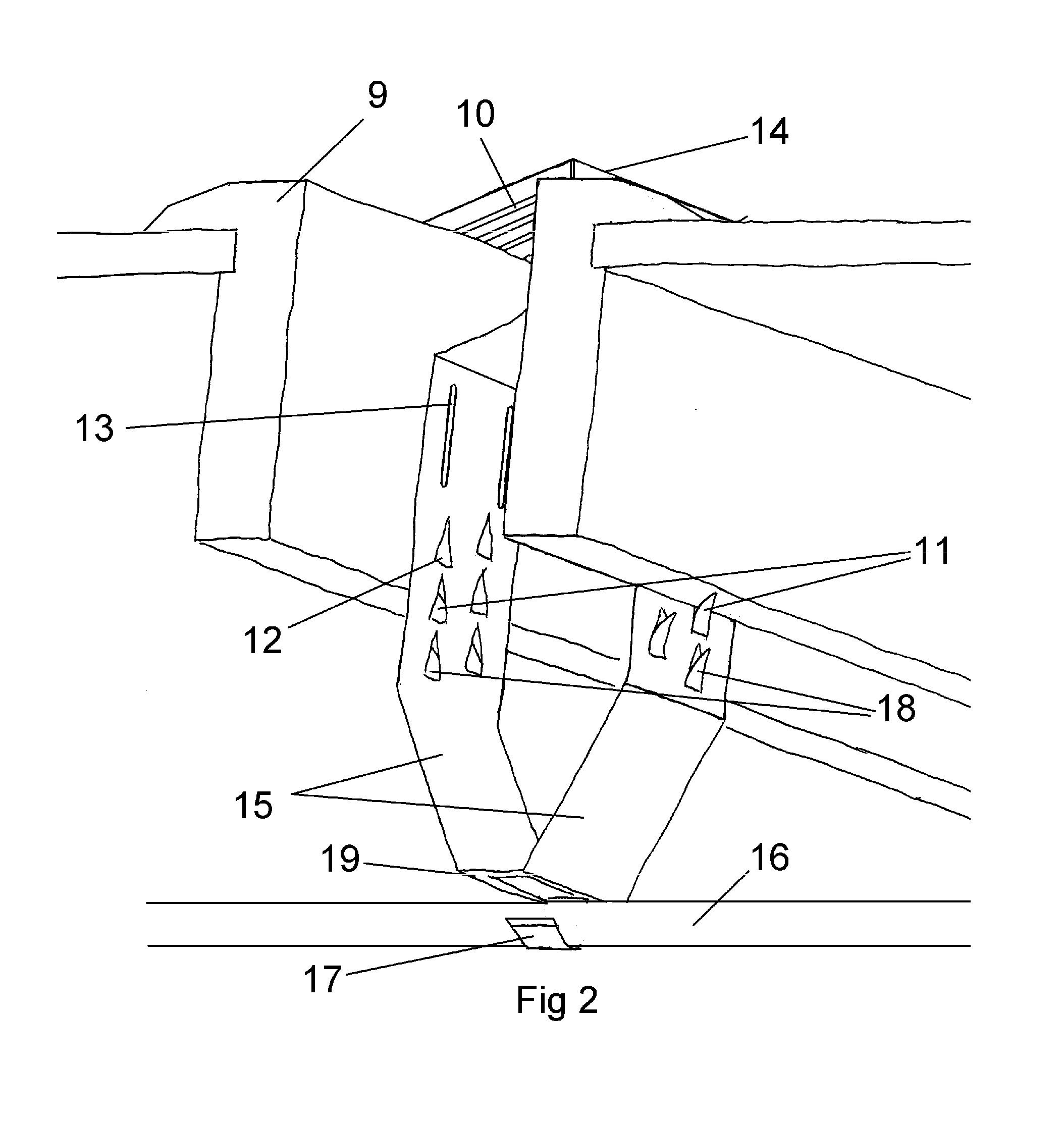
The solar grounding spring is a special spring that connects to a solar panel's frames. It has conductive contacts that penetrate the frames and surface retention springs that compress during installation and spring outward. The springs provide a secure and positive connection to the frames, ensuring good grounding. The spring can also be easily replaced and integrated a separate function into a single device. Overall, the solar grounding spring simplifies the installation process and improves the performance of solar panels.

Problems solved by technology

Specifically, the time consuming tasks of 1) connecting the washer, nut, and bolt of the ground lug to the solar panel's conductive frames or surfaces, 2) torque tightening the washer, nut, and bolt of the ground lug to the solar panel's conductive frames or surfaces, 3) inserting the separate ground wire into the then installed ground lug and 4) clamping the lug actuator or hardware to the ground wire.

Method used


Image

  • Solar Grounding Spring
  • Solar Grounding Spring
  • Solar Grounding Spring

Examples


Embodiment Construction

[0022]FIG. 7 and FIG. 9 illustrates features of prior art from authors Brian Thomas Wiley, Palvin Chee Leong Chan, patent U.S. Pat. No. 8,092,129 dated Jan. 10, 2012. The washer 3301 and 40 are formed from a flat metal piece and have four surface penetrating upward and downward facing circular rings 3300 and 41 that are used to penetrate the solar frame anodize. FIG. 7 shows how the washer is assembled and clamped to the solar frame assembly with a ground lug 3400, nut 1106, bolt 1100, and two additional washers 1104 and 1105. Once assembled to the solar frame assembly, a cable is then inserted into the ground lug and the clamping screw 3500 is tightened down onto it. This is repeated for each solar module. FIG. 9 shows how the washer 40 is assembled and clamped between the module frame 44 and racking 43 using the module mounting hardware, nuts (recessed in the rack 43), and bolts 42. Each of these figures shows the hardware and related torque dependencies necessary to secure these ...


PUM


Abstract

An improved method for bonding opposing parallel and perpendicular positioned electrically conductive frames or surfaces. An electrically conductive spring body formed and positioned in such a way as to provide opposing outward force to electrically adjoin the conductive frames or surfaces. The spring comprises outward facing surface penetrating contacts and surface retention springs that provide the electrical interface and positive capture of the spring to the conductive frames or surfaces. The spring can comprise a formed feature at the bottom tip of the device to capture a separate cable when the spring's tip is not being used for grounding to another surface.

Description

[0001]This application claims priority from the PROVISIONAL APPLICATION Ser. No. 61 / 553,213 which was filed Oct. 30, 2011 titled, “grounding spring” by Jeffrey David Roth.TITLE[0002]Solar Grounding SpringBACKGROUND OF THE INVENTION[0003]Solar modules often require electrical paths to ground (earth) to prevent equipment damage under lightning strikes and also to ensure public safety. Various connection devices are available to establish electrical contact between metal frames. Solar modules themselves are photovoltaic devices that convert solar radiation from the sun into electrical energy. Each solar module comprises a plurality of solar cells typically connected in series within a module frame. A plurality of modules may be connected together to form a solar panel array. The modules are typically positioned side by side and row to row on standard and repeated interval based on standard industry racking hardware. Typically, the aluminum solar module frames have a 0.001″ anodize surf...

Claims


Application Information

Patent Timeline
IPC IPC(8): H01R4/48
CPCH01R4/26H01R4/64H01R4/4809
Inventor ROTH, JEFFREY DAVID
Owner ROTH JEFFREY DAVID
Learn More