Self-inflating tire

a self-inflating, tire technology, applied in the direction of inflatable tyres, tire measurements, vehicle components, etc., can solve the problems of reducing vehicle braking and handling performance, tire life, and fuel economy

Inactive Publication Date: 2013-05-09
THE GOODYEAR TIRE & RUBBER CO
View PDF2 Cites 20 Cited by
  • Summary
  • Abstract
  • Description
  • Claims
  • Application Information

AI Technical Summary

Problems solved by technology

Accordingly, drivers must repeatedly act to maintain tire pressures or they will see reduced fuel economy, tire life and reduced vehicle braking and hand

Method used


Image

  • Self-inflating tire
  • Self-inflating tire
  • Self-inflating tire

Examples


Embodiment Construction

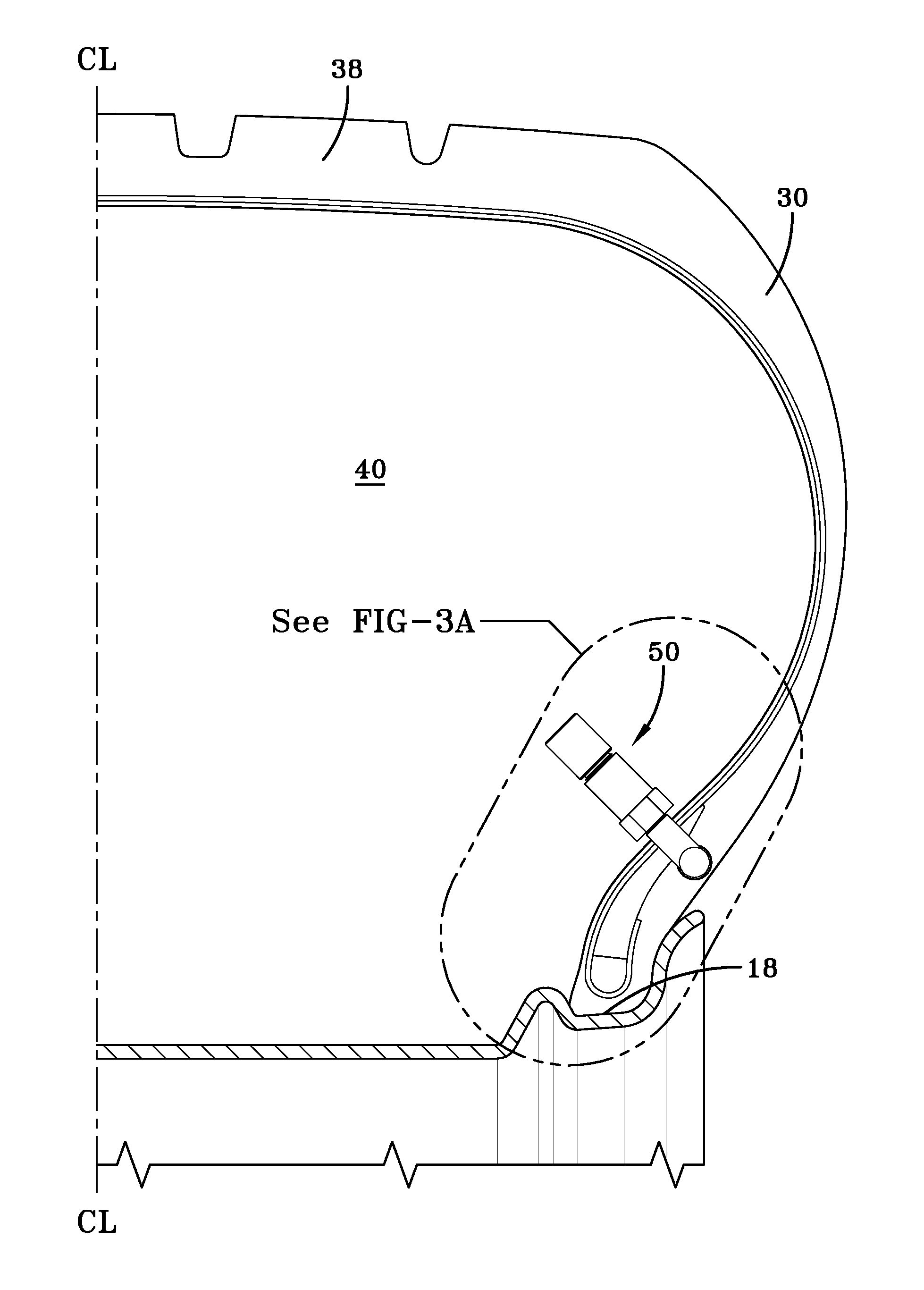
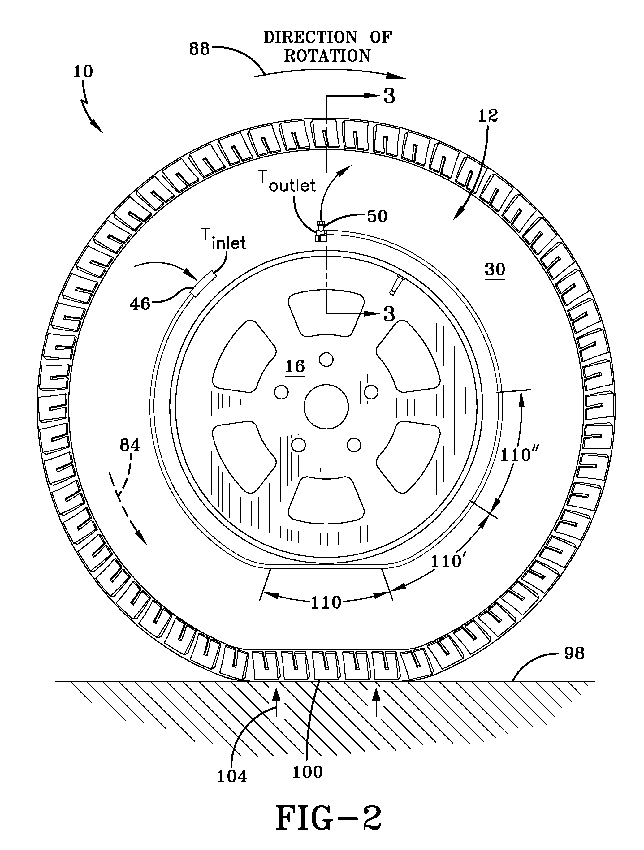
[0036]Referring to FIGS. 1 through 3, a tire assembly 10 includes a tire 12, a peristaltic pump assembly 14, and a tire rim 16. The tire mounts in a conventional fashion to a pair of rim mounting surfaces 18 located adjacent outer rim flanges 20. The outer rim flanges 20 have an outer rim surface 22 that engages the bead area of the tire. The tire is of conventional construction, having a pair of sidewalls 30 extending from opposite bead areas 34 to a crown or tire tread region 38. The tire and rim enclose a tire cavity 40.

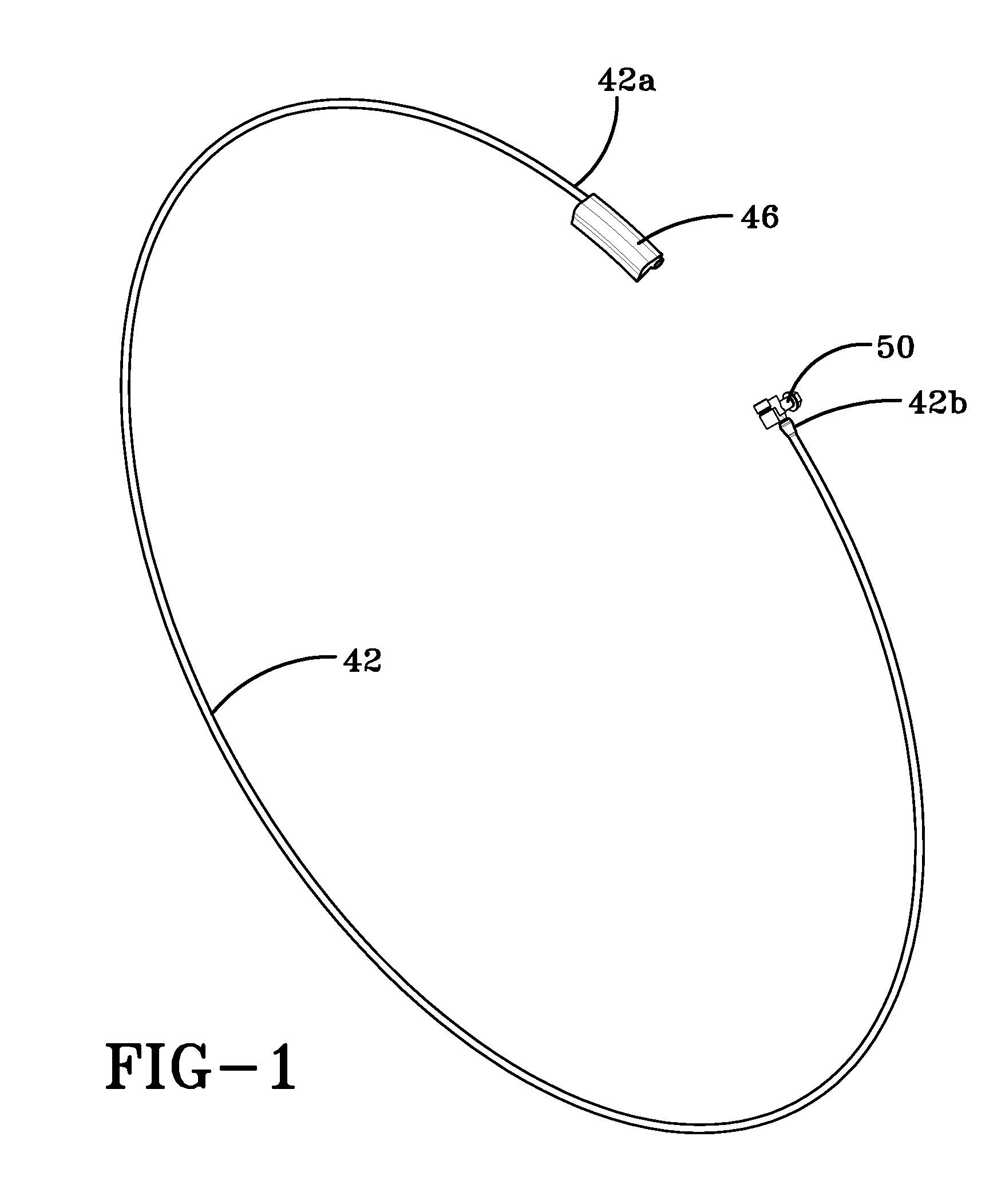
[0037]As shown in FIGS. 1-2, the peristaltic pump assembly 14 includes a pump tube 42 that is mounted in a tire passageway 44, which is preferably located in the sidewall area of the tire, preferably near the bead region. The tire passageway is preferably molded into the sidewall of the tire during vulcanization and is preferably annular in shape. The pump tube 42 has a first end 42a joined together by an inlet device 46 and a second end 42b joined together with a...


PUM


Abstract

A self-inflating tire assembly includes an air tube connected to a tire and defining an air passageway, the air tube being composed of a flexible material operative to allow an air tube segment opposite a tire footprint to flatten, closing the passageway, and resiliently unflatten into an original configuration. The air tube is sequentially flattened by the tire footprint in a direction opposite to a tire direction of rotation to pump air along the passageway to an inlet device for exhaust from the passageway or to an outlet device for direction into the tire cavity. The inlet device is positioned within the annular passageway 180 degrees opposite the outlet device such that sequential flattening of the air tube by the tire footprint effects pumping of air along the air passageway with the tire rotating in either a forward or reverse direction of rotation. The invention further includes an outlet device for regulating the tire cavity pressure and flow into the cavity.

Description

FIELD OF THE INVENTION[0001]The invention relates generally to self-inflating tires and, more specifically, to a pump mechanism for such tires.BACKGROUND OF THE INVENTION[0002]Normal air diffusion reduces tire pressure over time. The natural state of tires is under inflated. Accordingly, drivers must repeatedly act to maintain tire pressures or they will see reduced fuel economy, tire life and reduced vehicle braking and handling performance. Tire Pressure Monitoring Systems have been proposed to warn drivers when tire pressure is significantly low. Such systems, however, remain dependant upon the driver taking remedial action when warned to re-inflate a tire to recommended pressure. It is a desirable, therefore, to incorporate a self-inflating feature within a tire that will self-inflate the tire in order to compensate for any reduction in tire pressure over time without the need for driver intervention.Definitions[0003]“Aspect ratio” of the tire means the ratio of its section heig...

Claims


Application Information

Patent Timeline
IPC IPC(8): B60C19/00B60C5/00
CPCY10T152/10495B60C23/12B60C23/123B60C23/135
Inventor HINQUE, DANIEL PAUL LUC MARIELEVY, LOISBONNET, GILLES
Owner THE GOODYEAR TIRE & RUBBER CO
Why Eureka
Try Eureka