Injection mold cavity pressure control system and method

A control system and cavity technology, applied in the injection mold cavity pressure control system and control field, can solve problems such as the inability to meet periodic pressurization and pressure relief actions, so as to improve service life, improve efficiency, and ensure quality and finished products. rate effect

Active Publication Date: 2013-02-20
SHANDONG UNIV
View PDF8 Cites 19 Cited by
  • Summary
  • Abstract
  • Description
  • Claims
  • Application Information

AI Technical Summary

Problems solved by technology

This technology is mainly used in the control and adjustment of gas source pressure in the field of electric propulsion engines. Its main features are divided into two parts: the main pipeline pressure regulator and the sub pipeline pressure regulator, which can control multiple pipelines to work at the same time and realize real-time gas pipeline pressure Adjustable, but this technology cannot meet the requirements of periodic pressurization and pressure relief in the injection molding process, and is not suitable for the control of mold cavity pressure in the injection molding process

Method used


Image

  • Injection mold cavity pressure control system and method
  • Injection mold cavity pressure control system and method

Examples


Embodiment Construction

[0032] The present invention will be further described below in conjunction with the accompanying drawings and embodiments.

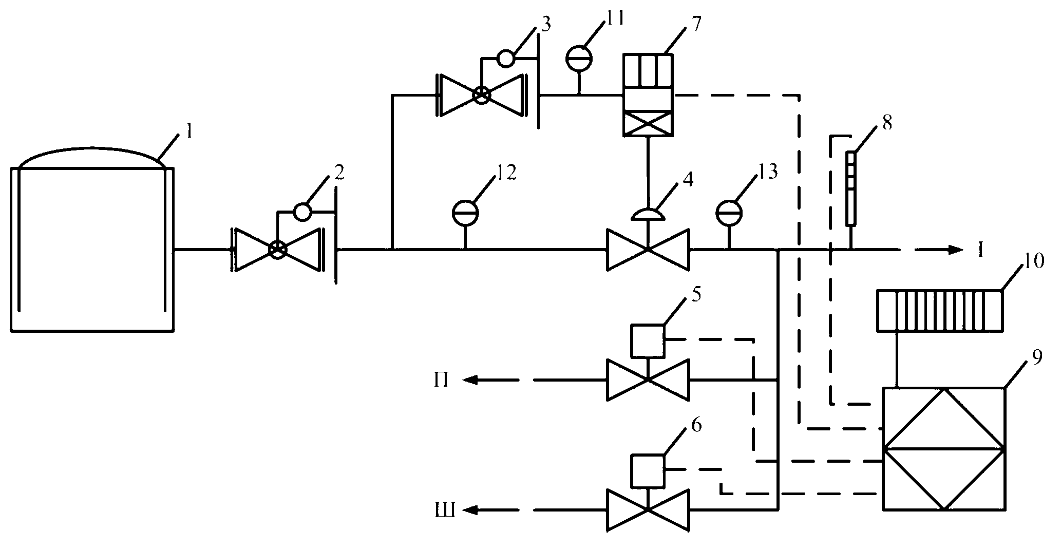
[0033] Such as figure 1 As shown, the injection mold cavity pressure control system and control method include a high-pressure nitrogen source 1. The high-pressure nitrogen source 1 is connected to the mold inlet through the air outlet I of the device after passing through the mold cavity pressure control device. The pipeline is close to There is a first pressure reducing valve 2 at the position of the high pressure nitrogen source 1, the pipeline is divided into two paths after passing through the first pressure reducing valve 2, and one path passes through the second pressure reducing valve 3, the first pressure gauge 11 and the electronic pressure controller 7 It is connected to the air control regulating valve 4, and the other path is connected to the air control regulating valve 4 through the second pressure gauge 12. The outlet of the air control ...


PUM


Abstract

The invention discloses an injection mold cavity pressure control system and method. The injection mold cavity pressure control system comprises a high-pressure nitrogen source, wherein the high-pressure nitrogen source is connected with a mould air inlet through a pipeline, a first pressure reducing valve is arranged on the part, which is close to the high-pressure nitrogen source, of the pipeline, the pipeline is divided into two paths after passing through the first pressure reducing valve, one path is connected with an air control regulating valve through a second pressure reducing valve, a first pressure meter and an electronic pressure controller, the other path is connected with the air control regulating valve through a second pressure meter, the outlet of the air control regulating valve is connected with the mould air inlet, a third pressure meter, a pressure sensor and a pressure relieving pipeline unit are sequentially arranged on the pipeline, the electronic pressure controller, the pressure relieving pipeline unit and the pressure sensor are connected with a data processing and controlling system, and the data processing and controlling system is connected with an injection molding machine signal unit. The invention also discloses a control method of the injection mold cavity pressure control system. The injection mold cavity pressure control system has the characteristics of high pressurizing rate and pressure relieving rate of a mould cavity, capabilities of maintaining high pressure of the mould cavity and controlling the acting time of the high pressure of the mould cavity, and the like.

Description

technical field [0001] The invention relates to a gas pressure control system and a control method, in particular to an injection mold cavity pressure control system and a control method. Background technique [0002] In the development process of the plastics industry, in order to achieve the purpose of improving product size accuracy, reducing product quality, shortening molding cycle, and saving energy, some new injection molding methods have gradually emerged, such as structural foam injection molding, multi-component injection molding, and reaction molding. Injection molding, exhaust injection molding, micro-foaming injection molding, gas-assisted injection molding, vibration injection molding, micro-injection molding, etc. [0003] Due to the shrinkage of the melt during the cooling process and the uneven distribution of the holding pressure during the holding process of the parts made by conventional injection molding methods, the molded products have defects such as ...

Claims


Application Information

Patent Timeline
Patent Type & Authority Applications(China)
IPC IPC(8): B29C45/76
Inventor 赵国群李帅管延锦
Owner SHANDONG UNIV
Why Eureka
Try Eureka