
Fuel cell system

A fuel cell system and fuel cell technology, used in fuel cells, fuel cell additives, solid electrolyte fuel cells, etc., can solve the problems of not being able to continue to generate electricity and heat, and achieve the effect of reducing pressure damage

Active Publication Date: 2012-03-07
PANASONIC CORP
View PDF9 Cites 4 Cited by
  • Summary
  • Abstract
  • Description
  • Claims
  • Application Information

AI Technical Summary

Problems solved by technology

Therefore, it is impossible to continue to generate electricity and heat by means of the fuel cell system

Method used


Image

  • Fuel cell system
  • Fuel cell system
  • Fuel cell system

Examples


Embodiment approach 1

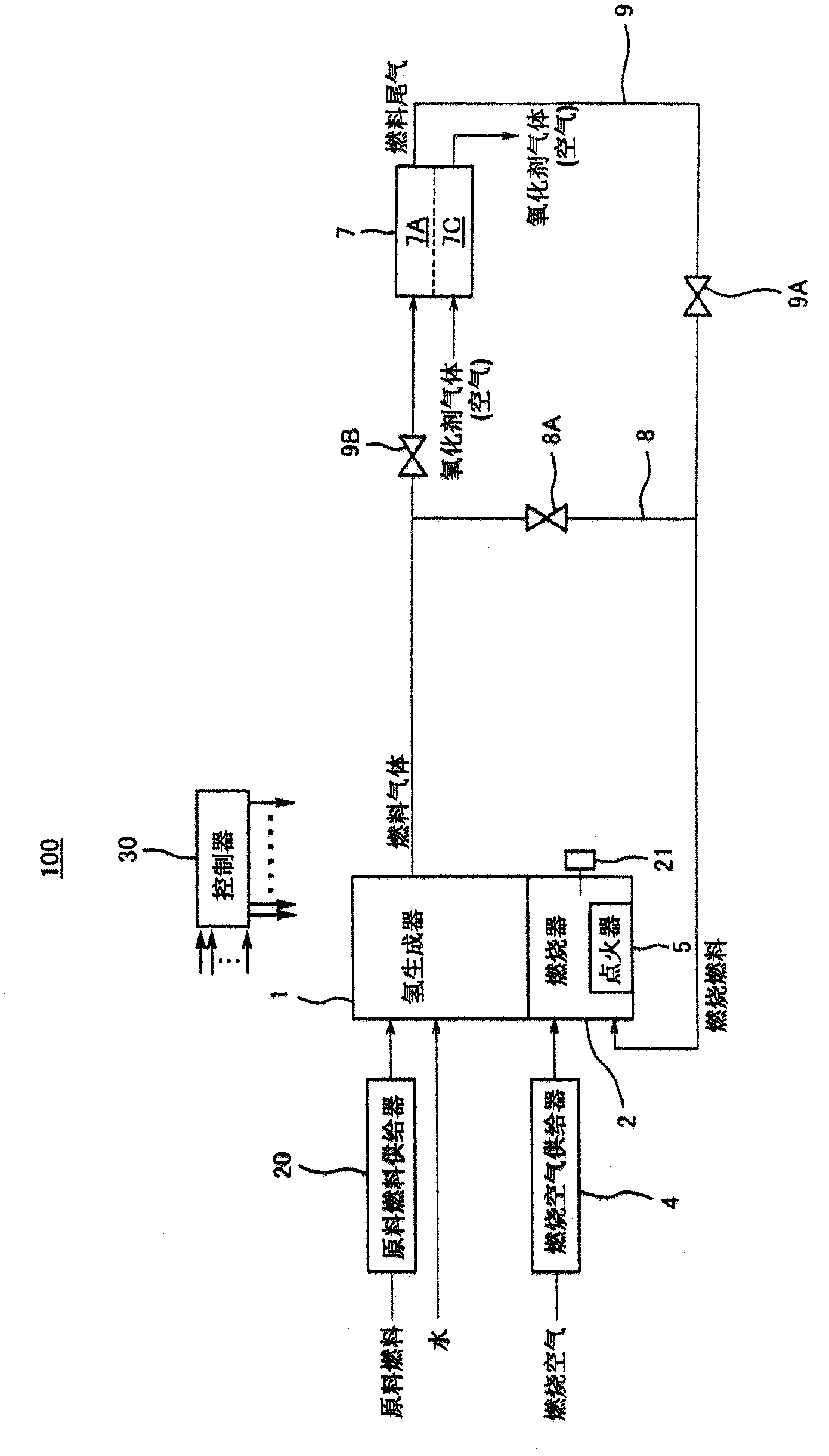
[0090] The following is a reference to the attached Figure 1 Next, a specific configuration example and operation example of the fuel cell system according to Embodiment 1 of the present invention will be described.

[0091] However, the following detailed description is merely an illustration of the characteristics of each of the fuel cell systems described above. For example, in the case of describing the following specific examples by assigning appropriate reference signs to the same terms as those specifying the respective fuel cell systems described above, the specific device is one of the constituent elements of the respective fuel cell systems described above. example.

[0092] Therefore, the characteristics of each fuel cell system described above are not limited by the following detailed description.

[0093] [Structure Example of Fuel Cell System]

[0094] figure 1 It is a block diagram showing a configuration example of the fuel cell system according to Embodim...

Embodiment approach 2

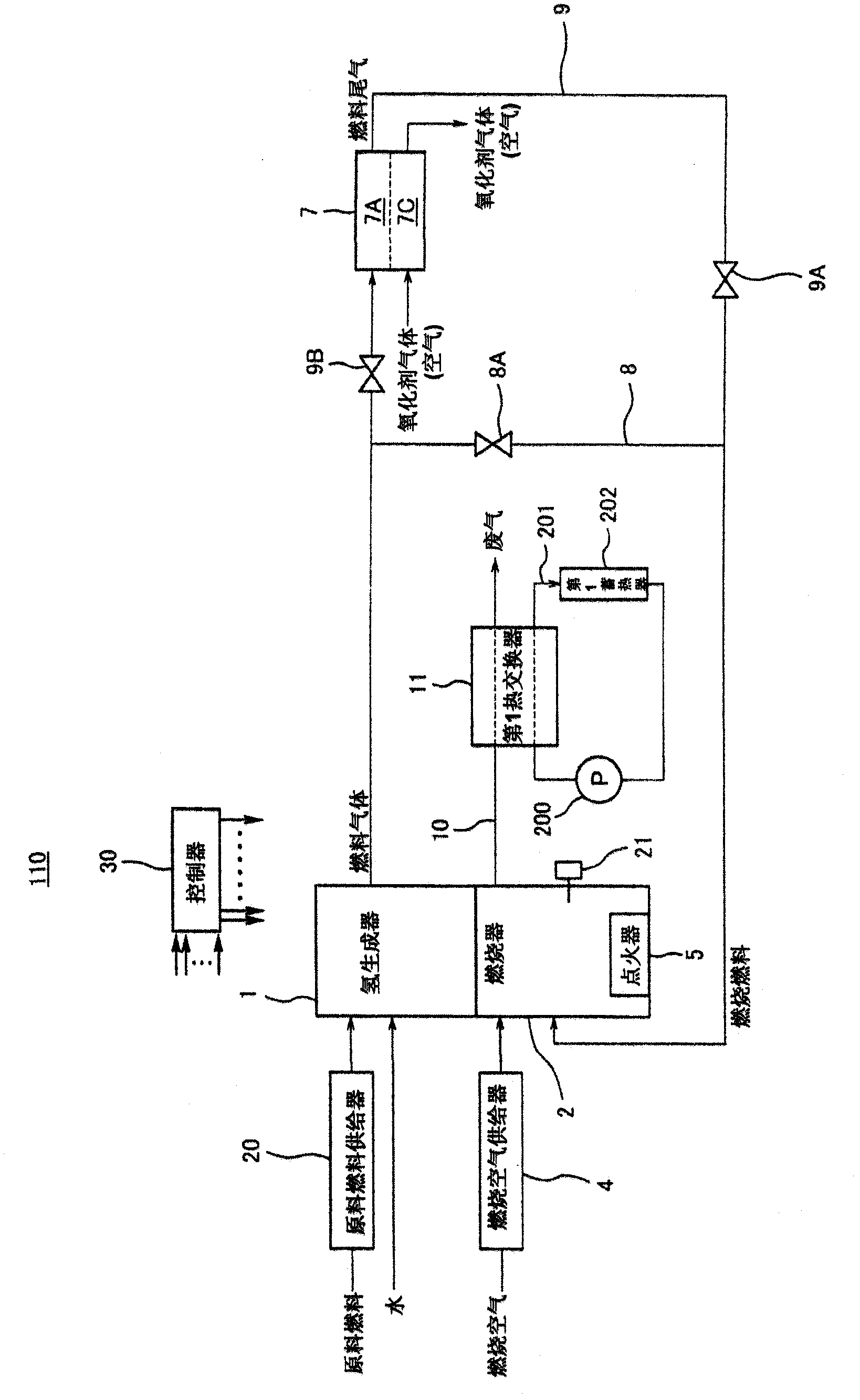
[0171] The following is a reference to the attached Figure 1 A specific configuration example and operation example of the fuel cell system according to Embodiment 2 of the present invention will be described.

[0172] However, the following detailed description is merely an example of the features of each fuel cell system listed at the beginning of the "Detailed Description of Embodiments" column. For example, in the case of describing the following specific examples by assigning appropriate reference signs to the same terms as those specifying the above-mentioned respective fuel cell systems, the specific device is one of the constituent elements of the above-mentioned respective fuel cell systems corresponding thereto. example.

[0173] Therefore, the characteristics of each fuel cell system described above are not limited by the following detailed description.

[0174] [Structure Example of Fuel Cell System]

[0175] figure 2 It is a block diagram showing a configura...


PUM


Abstract

A fuel cell system (100) according to the present invention includes: a hydrogen generator (1) configured to generate a fuel gas through a reforming reaction by using a raw fuel; a fuel cell (7) configured to generate power by using the fuel gas; a combustor (2) configured to heat the hydrogen generator (1); at least one on-off valve (9A, 9B) configured to open / block a gas passage (9) through which the gas that is sent out from the hydrogen generator (1) is supplied to the combustor (2); and a combustion air supply device (4) configured to supply combustion air to the combustor (2); an ignition device (5) provided at the combustor (2), and a controller (30). The combustor (2) is configured to perform combustion during power generation of the fuel cell (7) by using the gas supplied through the gas passage (9). In a case where accidental flame extinction has occurred at the combustor (2) during the power generation of the fuel cell (7), the controller (30) performs an ignition operation of the ignition device (5) with the on-off valve (9A, 9B) kept opened.

Description

technical field [0001] The present invention relates to fuel cell systems. In particular, the present invention relates to a fuel cell system for generating electricity using hydrogen-rich gas produced by steam reforming reactions using hydrocarbons such as natural gas, LPG, gasoline, naphtha, kerosene, and methanol as the main raw material (raw material fuel) . Background technique [0002] In the hydrogen generator of the fuel cell system, a raw material fuel containing an organic compound composed of carbon atoms and hydrogen atoms is steam-reformed in a reformer equipped with a reforming catalyst layer. A hydrogen-rich gas (hereinafter abbreviated as "hydrogen gas" and sometimes abbreviated as "fuel gas") is produced as a reformed gas by this reforming reaction. [0003] In the fuel cell of the fuel cell system, electricity and heat are generated by using the above-mentioned hydrogen gas and reacting the hydrogen gas with an oxidant gas such as air. [0004] Under amb...

Claims


Application Information

Patent Timeline
Patent Type & Authority Applications(China)
IPC IPC(8): H01M8/06H01M8/04H01M8/10
CPCC01B3/384C01B3/48C01B2203/0233C01B2203/0283C01B2203/066C01B2203/0822C01B2203/0827C01B2203/1217C01B2203/1235H01M8/04022H01M8/04686H01M8/04955H01M8/0618Y02E60/50Y02P20/10
Inventor 田村佳央田口清楠村浩一保田繁树
Owner PANASONIC CORP
Learn More