Transmission cavity pressure control system and method

A technology of control system and transmission cavity, which is applied in the field of semiconductor processing technology, can solve the problems of increasing nitrogen consumption and increasing the cost of use, and achieves the effect of low nitrogen consumption and stable pressure control

Inactive Publication Date: 2009-07-01
BEIJING NAURA MICROELECTRONICS EQUIP CO LTD
View PDF0 Cites 19 Cited by
  • Summary
  • Abstract
  • Description
  • Claims
  • Application Information

AI Technical Summary

Problems solved by technology

And if you want to shorten the adjustment time of pressure control, you need to increase the pumping

Method used


Image

  • Transmission cavity pressure control system and method
  • Transmission cavity pressure control system and method

Examples


Embodiment Construction

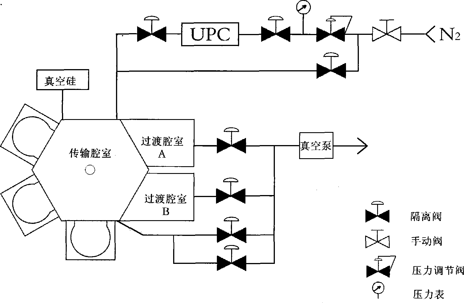
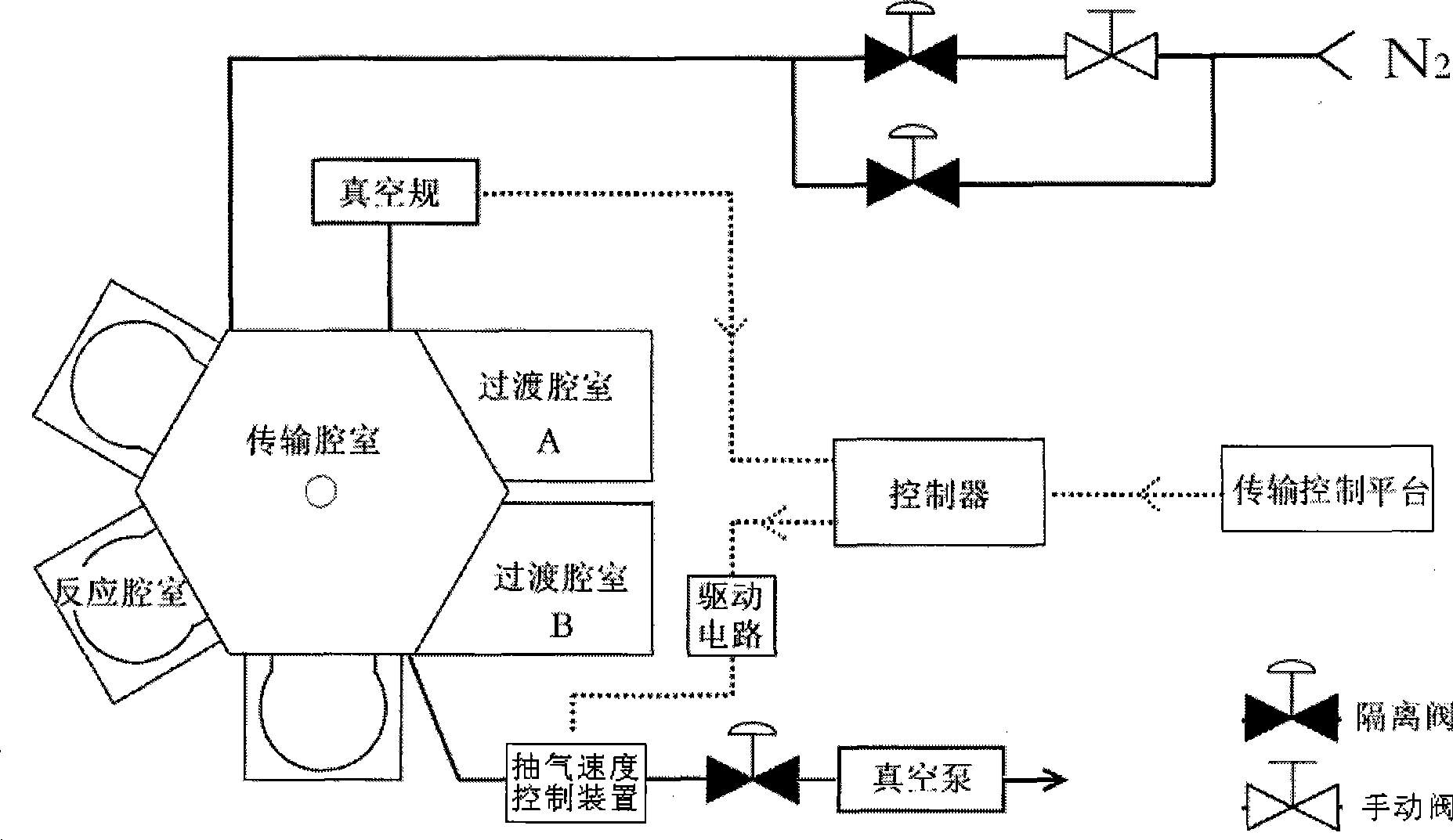
[0015] The preferred embodiment of the transmission chamber pressure control system of the present invention is as follows: figure 2 As shown in the figure, the transmission chamber is provided with an air-filling air circuit and a vacuuming air circuit. Nitrogen is charged into the transmission chamber through the air-inflating air circuit. maintain the required vacuum.

[0016] A pumping speed control device is provided on the vacuuming air circuit, which is used to control the pumping speed of the vacuuming air circuit, and then control the pressure in the transmission chamber.

[0017] The pumping speed control device may be connected with a controller, and the transfer chamber is provided with a pressure sensor, and the pressure sensor is connected with the controller. The pressure sensor may be a vacuum gauge, and the pumping speed control device may be a pendulum valve or a butterfly valve. The pressure signal in the transmission chamber can be detected by the vacuum...


PUM


Abstract

The invention discloses a pressure control system of a transmission chamber and a method thereof. The transmission chamber is equipped with a charging air passage and an evacuating air passage, wherein the evacuating air passage is provided with an evacuating speed control device, and pressure in the transmission chamber is controlled through controlling evacuating speed of the evacuating air passage in the transmission chamber. The evacuating speed control device is connected with a controller, the transmission chamber is equipped with a pressure sensor connected with the controller, firstly detecting pressure signals in the transmission chamber, then comparing the pressure signals with the set pressure parameters, and on-line adjusting the evacuating speed of the evacuating air passage in real time through closed-loop control algorithms such as PID and the like, finally, the purpose of control pressure in the transmission chamber is achieved. Besides, the system is stable in pressure control and low in nitrogen consumption.

Description

technical field [0001] The present invention relates to a semiconductor processing technology, in particular to a pressure control system and method of a transfer chamber. Background technique [0002] In the semiconductor processing technology, the semiconductor equipment performs some kind of treatment on the substrate through physical, chemical and other means. The processing of substrates by semiconductor equipment is usually performed in a closed reaction chamber under a vacuum environment. In addition to the reaction chamber, the semiconductor equipment usually also includes a transfer chamber, which is connected with the reaction chamber, and is equipped with a vacuum manipulator, which is responsible for accurately transferring the substrates to each reaction chamber. Therefore, when the equipment is working, the vacuum environment must also be maintained in the transfer chamber. Because the transfer chamber and the process reaction chamber are in direct communicat...

Claims


Application Information

Patent Timeline
IPC IPC(8): G05D16/14G05D16/20H01L21/677
Inventor 刘畅
Owner BEIJING NAURA MICROELECTRONICS EQUIP CO LTD
Why Eureka
Try Eureka