
Switch device

Active Publication Date: 2013-05-09
NITTEI MUSEN +1
View PDF4 Cites 1 Cited by
  • Summary
  • Abstract
  • Description
  • Claims
  • Application Information

AI Technical Summary

Benefits of technology

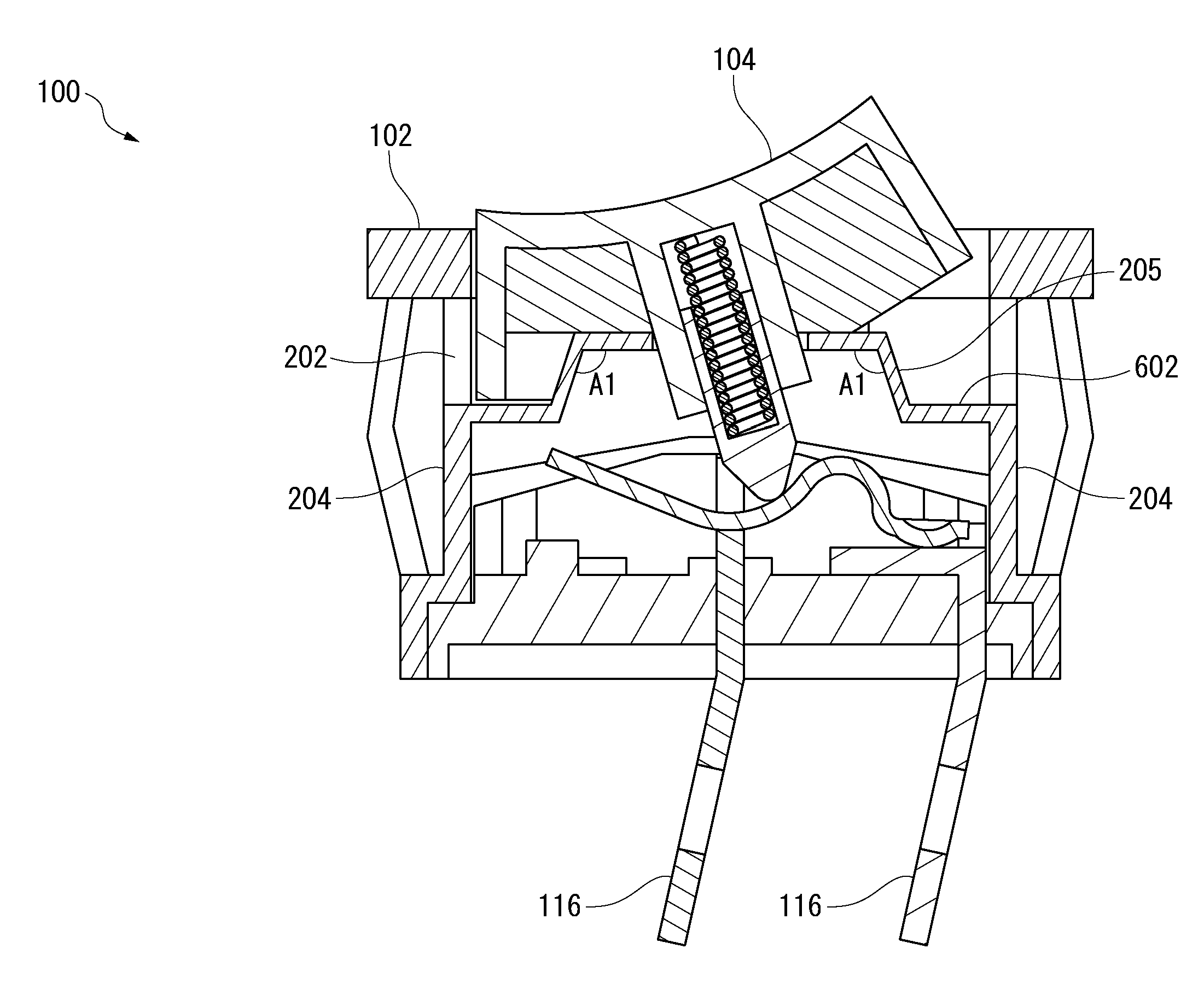
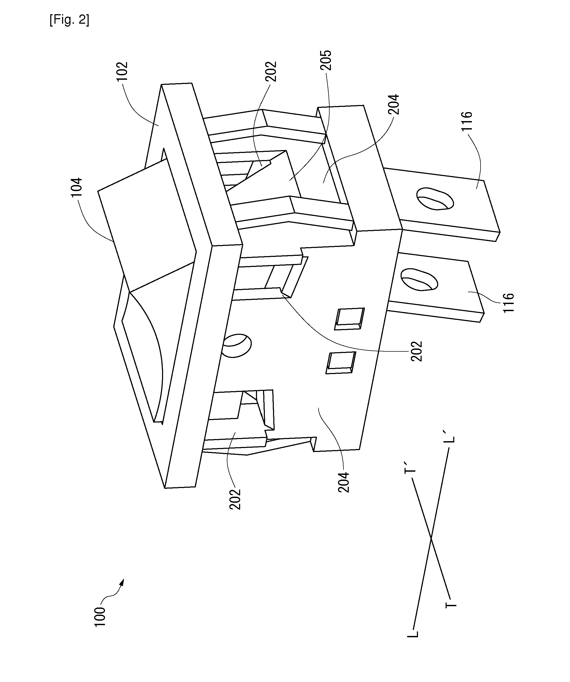
The present invention is a switch device for a hand-held power tool that protects the operational member and the contact member without any complicated construction or decreasing the overall efficiency of the switch device. It includes a chamber with a hole on its side walls that provides a passageway for the discharge of the external particulate material encountered during an operation of the power tool. The bottom surface of the chamber is also at least partly sloped which facilitates the enhanced discharge of the external particulate materials through the hole. This switch device can be easily integrated into any existing switch device that includes a hole around its housing.

Problems solved by technology

These external particulate materials may affect the overall performance of the switch device.

Method used


Image

  • Switch device
  • Switch device
  • Switch device

Examples


Embodiment Construction

[0026]The present invention will be described more fully hereinafter with reference to the accompanying drawings, in which example embodiments of the invention incorporating one or more aspects of the present invention are shown. This invention may, however, be embodied in many different forms and should not be construed as limited to the embodiments set forth herein; rather, these embodiments are provided so that this disclosure will be thorough and complete, and will fully convey the scope of the invention to those skilled in the art. For example, one or more aspects of the present invention can be utilized in other embodiments and even other types of devices. In the drawings, like numbers refer to like elements.

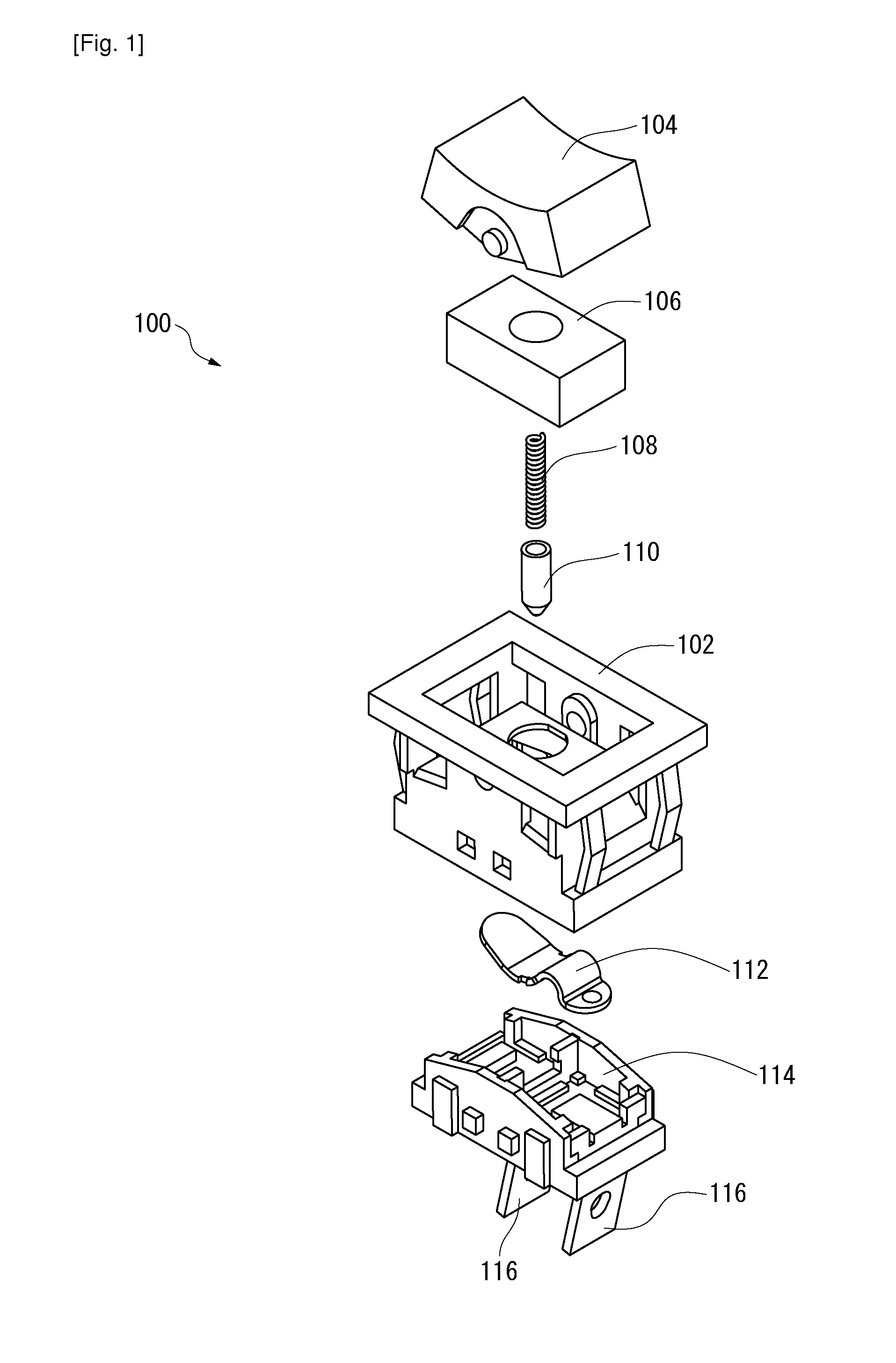
[0027]FIG. 1 illustrates an exploded view of an exemplary switch device 100, according to a first exemplary embodiment of the present invention. Although the described example in FIG. 1 is a rocker switch device, it should be understood that the present invention could be ...


PUM


Abstract

The present invention relates to a switch device (100) for use in hand-held power tools. The switch device (100) may include at least one chamber (102) whose interior serves as an accommodation space. The chamber (102) may partially encase an operational member (104) for actuating the hand-held power tool through the switch device (100). Further, the switch device (100) is provided with multiple holes (202) on side walls (204) of the chamber (102) to create a passageway for external particulate materials. Also, a bottom surface (205) of the chamber (102) may be sloped to extend from an interior of the chamber (102) to each of the multiple holes (202), to enhance the discharging of the external particulate materials through the holes (202).

Description

TECHNICAL FIELD[0001]The present invention relates to a switch device, more particularly to a switch device for a hand-held power driven working tool.BACKGROUND ART[0002]A hand-held power tool, such as a chain saw, may use a switch device for actuation of electrical supply in the hand-held power tool. Generally, rocker type switch device are used in the hand-held power tools. However, other types of switch device, such as, but not limited to, toggle switch device, push button switch device, momentary switch device, or the like may also be used in similar operations.[0003]The switch devices used in the hand-held power tool include one or more chambers to accommodate an operational member and a contact member. The hand-held power tool may encounter external particulate materials around / into the switch device while the hand-held power tool is in operation. The external particulate materials may include saw dust, dirt, or the like. These external particulate materials may affect the ove...

Claims


Application Information

Patent Timeline
IPC IPC(8): H01H9/04
CPCH01H23/06H01H9/047H01H23/205
Inventor HARADA, ATSUSHIKAMAGOME, KOHKIARAI, KIYOTSUGU
Owner NITTEI MUSEN
Learn More