Fuel cell system

Inactive Publication Date: 2015-01-01
NISSAN MOTOR CO LTD
View PDF3 Cites 1 Cited by
  • Summary
  • Abstract
  • Description
  • Claims
  • Application Information

AI Technical Summary

Benefits of technology

[0006]However, it has been discovered that, depending on the operating condition, the aforementioned conventional fuel cell system creates a stagnation point where the anode gas concentration is locally low in an anode gas flow channel inside a fuel cell. It has also be

Problems solved by technology

However, it has been discovered that, depending on the operating condition, the aforementioned conventional fuel cell system creates a stagnation point where the anode gas concentration is locally low in an anode gas flow channel inside a fuel cell.
It has also been

Method used


Image

  • Fuel cell system
  • Fuel cell system
  • Fuel cell system

Examples


Example

First Embodiment

[0025]A fuel cell includes an electrolyte membrane interposed between an anode electrode (fuel electrode) and a cathode electrode (oxidant electrode), and generates power by supplying anode gas (fuel gas) containing hydrogen to the anode electrode and cathode gas (oxidant gas) containing oxygen to the cathode electrode. The following electrode reactions proceed in the anode electrode and the cathode electrode.

Anode Electrode: 2H2→4H++4e−  (1)

Cathode Electrode: 4H++4e−+O2→2H2O  (2)

[0026]The fuel cell generates an electromotive force of approximately one volt by these electrode reactions (1) and (2).

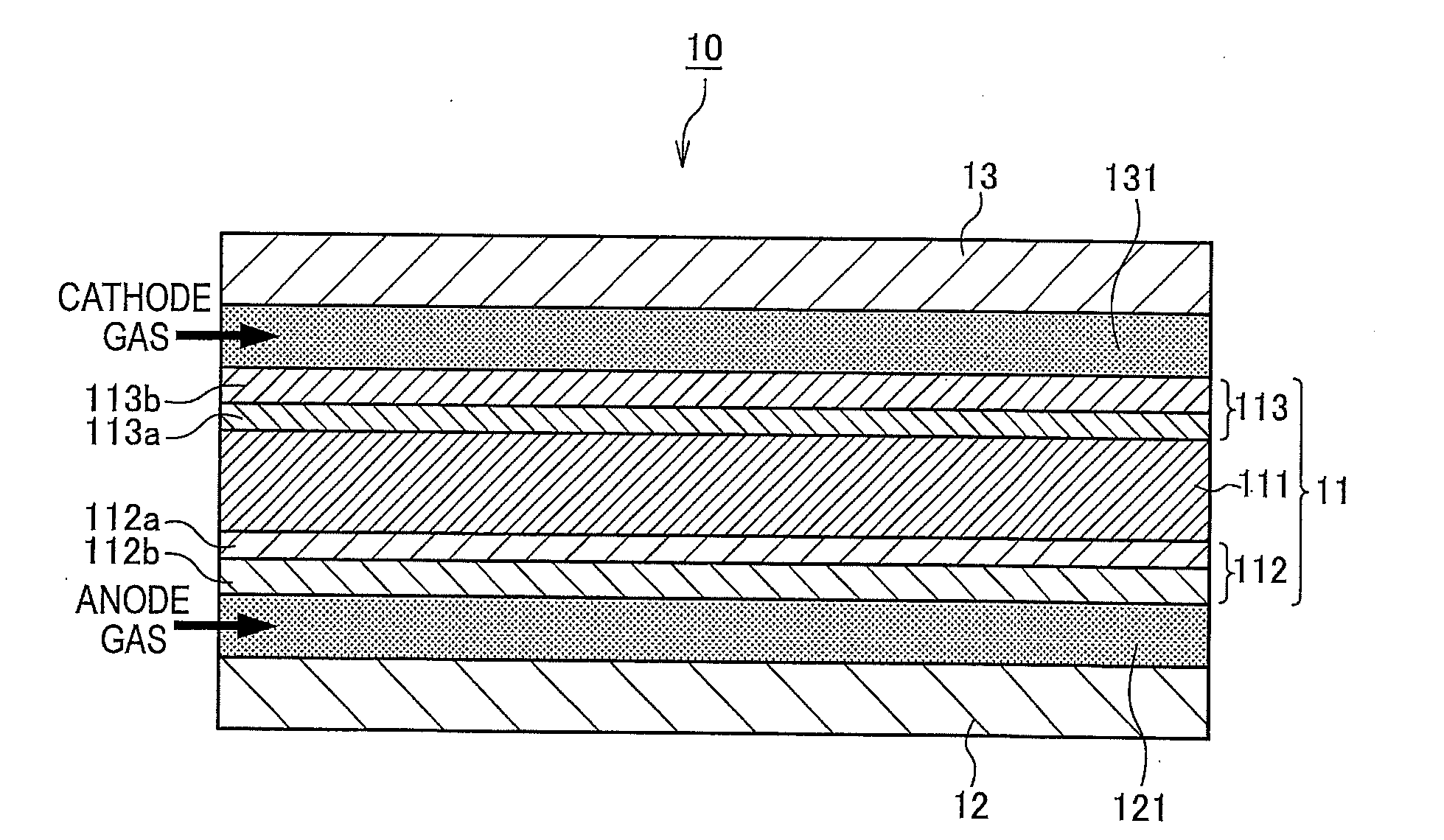
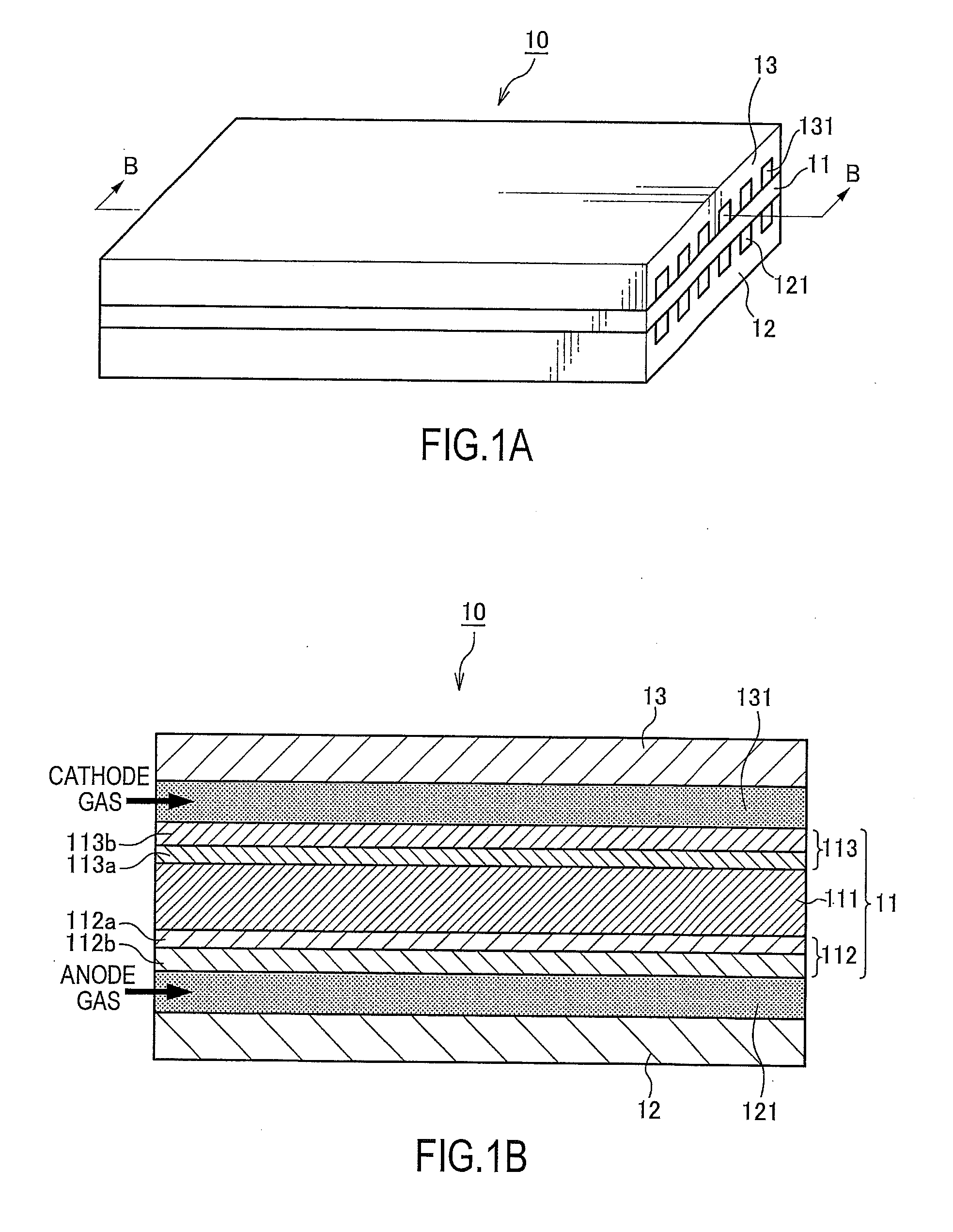
[0027]FIGS. 1A and 1B are explanatory diagrams showing a configuration of a fuel cell 10 according to a first embodiment of the present invention. FIG. 1A is a schematic perspective view of the fuel cell 10. FIG. 1B is a cross-sectional view of the fuel cell 10 shown in FIG. 1A taken along the line B-B.

[0028]The fuel cell 10 is configured such that an anode separator 12 and...

Example

Second Embodiment

[0102]A description is now given of a second embodiment of the present invention. The present embodiment differs from the first embodiment in that a larger criterion value C0 is set for a larger normal anode pressure upper limit value, P. The following description will be given with a focus on this difference. It should be noted that, in the embodiments described below, the elements that are similar to those of the above-described first embodiment in terms of function are given the same reference signs thereas, and redundant descriptions are omitted as appropriate.

[0103]When an instruction for increasing anode pressure is issued during the down transient operation, basically, the normal anode pressure upper limit value, P, is set in accordance with the operating condition of the fuel cell system 1.

[0104]When the down transient operation is re-executed after the anode pressure has been increased to the normal anode pressure upper limit value, P, the larger the normal...

Example

Third Embodiment

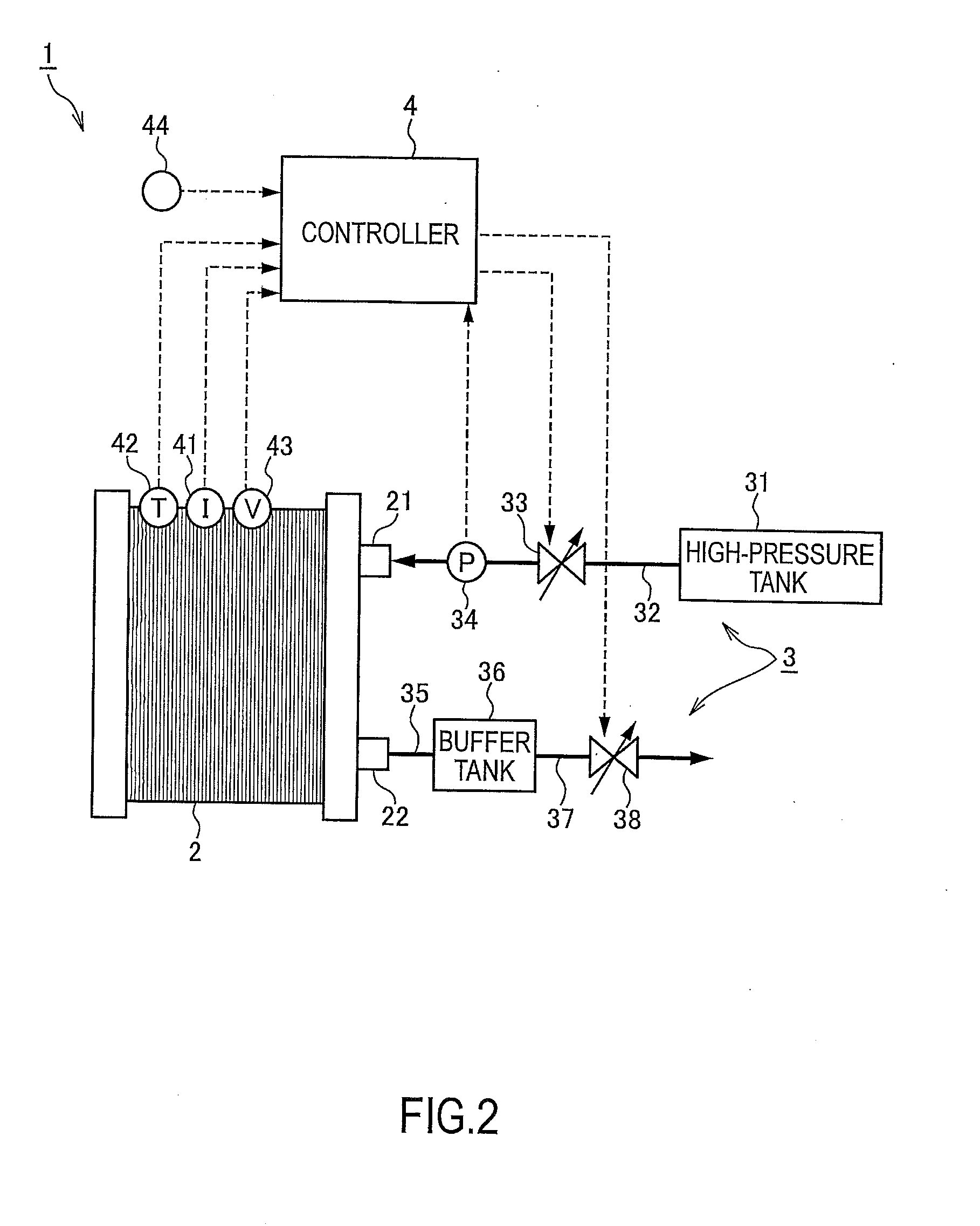
[0110]A description is now given of a third embodiment of the present invention. The present embodiment differs from the first embodiment in that, once the anode pressure has been increased to the anode pressure upper limit value for exhausting the stagnation point, P1, after the down transient operation, the anode pressure is restored to the normal anode pressure upper limit value, P, based on the anode gas concentration in the buffer tank 36. The following description will be given with a focus on this difference.

[0111]As stated earlier, the controller 4 regulates the opening degree of the purge valve 38 in accordance with the operating condition of the fuel cell system 1 so as to control the buffer concentration (the anode gas concentration in the buffer tank 36) Cbuff to be equal to a desired management concentration corresponding to the operating condition of the fuel cell system 1.

[0112]If the buffer concentration Cbuff becomes lower than this management concen...


PUM


Abstract

A fuel cell system that generates power by supplying anode gas and cathode gas to a fuel cell has a control valve that controls pressure of the anode gas supplied to the fuel cell, a pulsation operation unit that causes pulsation of pressure of anode gas in the fuel cell in accordance with a predetermined pressure by controlling an opening degree of the control valve based on an operating condition of the fuel cell system, and a stagnation point determination unit that determines, based on a change in the pressure of the anode gas in the fuel cell, whether or not a stagnation point exists where an anode gas concentration is locally low in the fuel cell. When the stagnation determining unit determines that the stagnation point exists in the fuel cell, the pulsation operation unit increases the predetermined pressure in execution of a pulsation operation.

Description

BACKGROUND[0001]1. Technical Field[0002]The present invention relates to a fuel cell system.[0003]2. Related Art[0004]JP-A-2007-517369 describes a conventional fuel cell system in which a normally-closed solenoid valve is provided to an anode gas supply passage, and a normally-open solenoid valve and a buffer tank (recycle tank) are provided to an anode gas exhaust passage such that the former is positioned upstream relative to the latter.[0005]This conventional fuel cell system does not circulate anode gas, that is to say, does not supply unused anode gas exhausted to the anode gas exhaust passage back to the anode gas supply passage. In this fuel cell system, unused anode gas accumulated in the buffer tank is recycled by causing it to flow back to a fuel cell stack through periodical opening and closing of the normally-closed solenoid valve and the normally-open solenoid valve.SUMMARY OF INVENTION[0006]However, it has been discovered that, depending on the operating condition, the...

Claims


Application Information

Patent Timeline
IPC IPC(8): H01M8/04
CPCH01M8/04104H01M8/04753H01M8/04388H01M8/04082H01M8/04179H01M8/04447H01M8/04679H01M8/04798H01M2008/1095Y02E60/50H01M8/04231
Inventor IKEZOE, KEIGOCHIKUGO, HAYATOMAKINO, SHINICHI
Owner NISSAN MOTOR CO LTD
Why Eureka
Try Eureka