Reverse osmosis filter flush device and method

Inactive Publication Date: 2013-08-01
SHUMWAY SCOTT
View PDF4 Cites 4 Cited by
  • Summary
  • Abstract
  • Description
  • Claims
  • Application Information

AI Technical Summary

Benefits of technology

[0002]The reverse osmosis membrane is well suited to, and accepted for, purifying a variety of liquids, including sea water, ground water, and the like. However, the input surface of the membrane against which the pressurized input fluid to

Problems solved by technology

However, the input surface of the membrane against which the pressurized input fluid to be purified is forced against and through becomes clogged of solid materials which have been filtered out to produce product liquid.
However, none of these disclose the present system or method, nor do these references approach the relatively high efficiency achieved with the present system, both in terms of being devoid of downtime, as well as the unique and highly

Method used


Image

  • Reverse osmosis filter flush device and method
  • Reverse osmosis filter flush device and method
  • Reverse osmosis filter flush device and method

Examples


Embodiment Construction

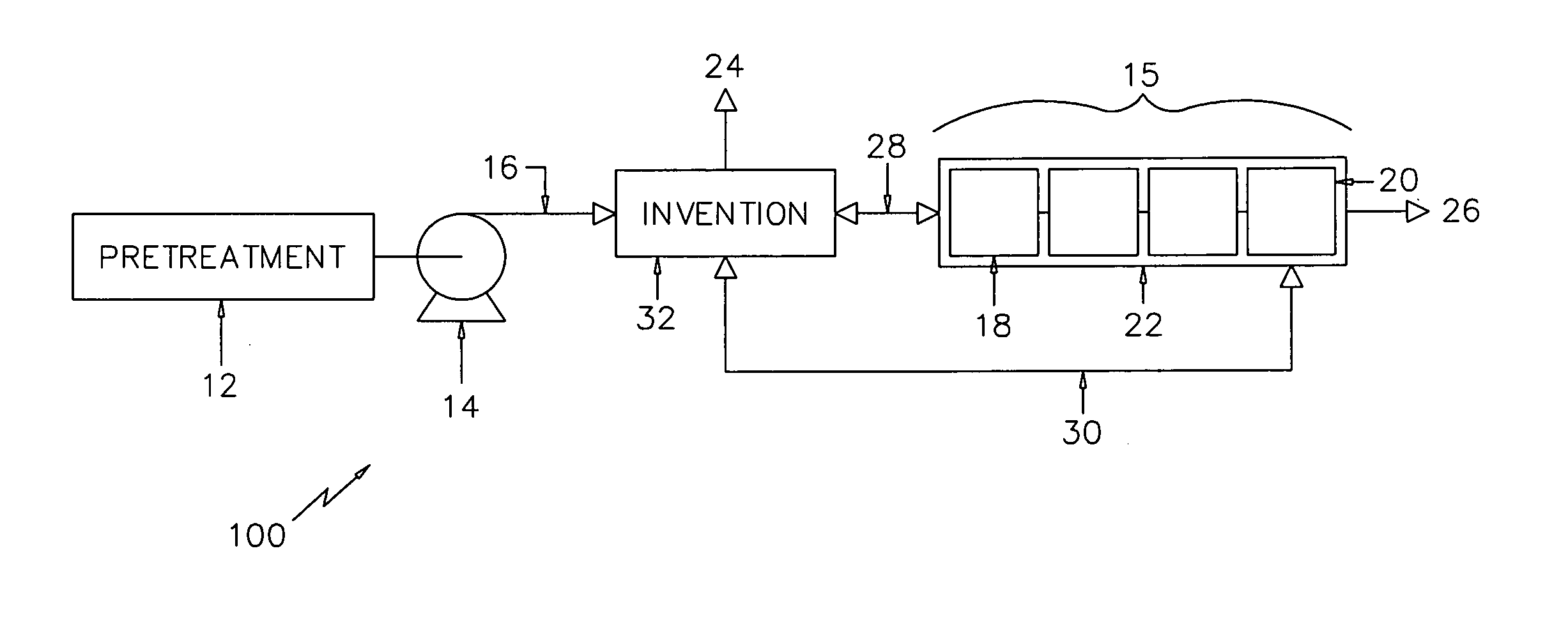
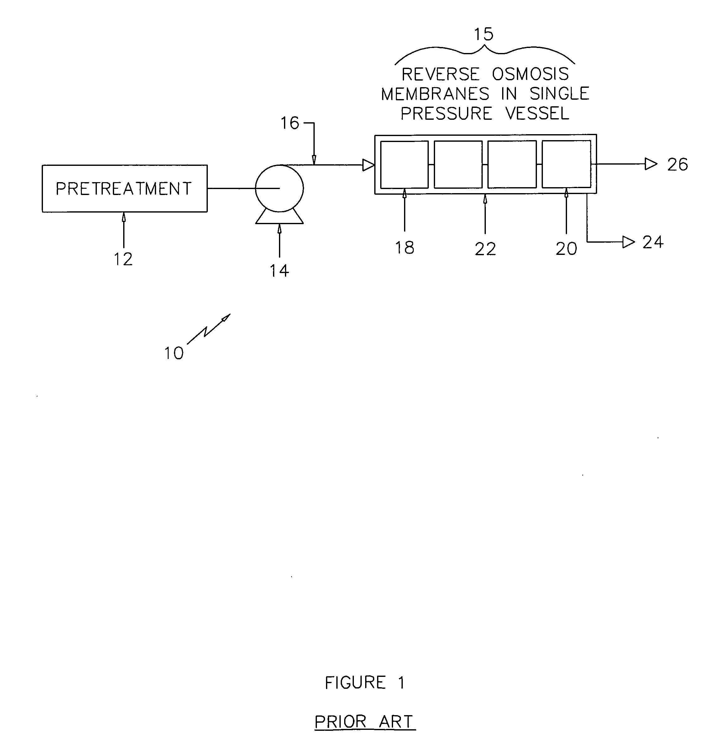
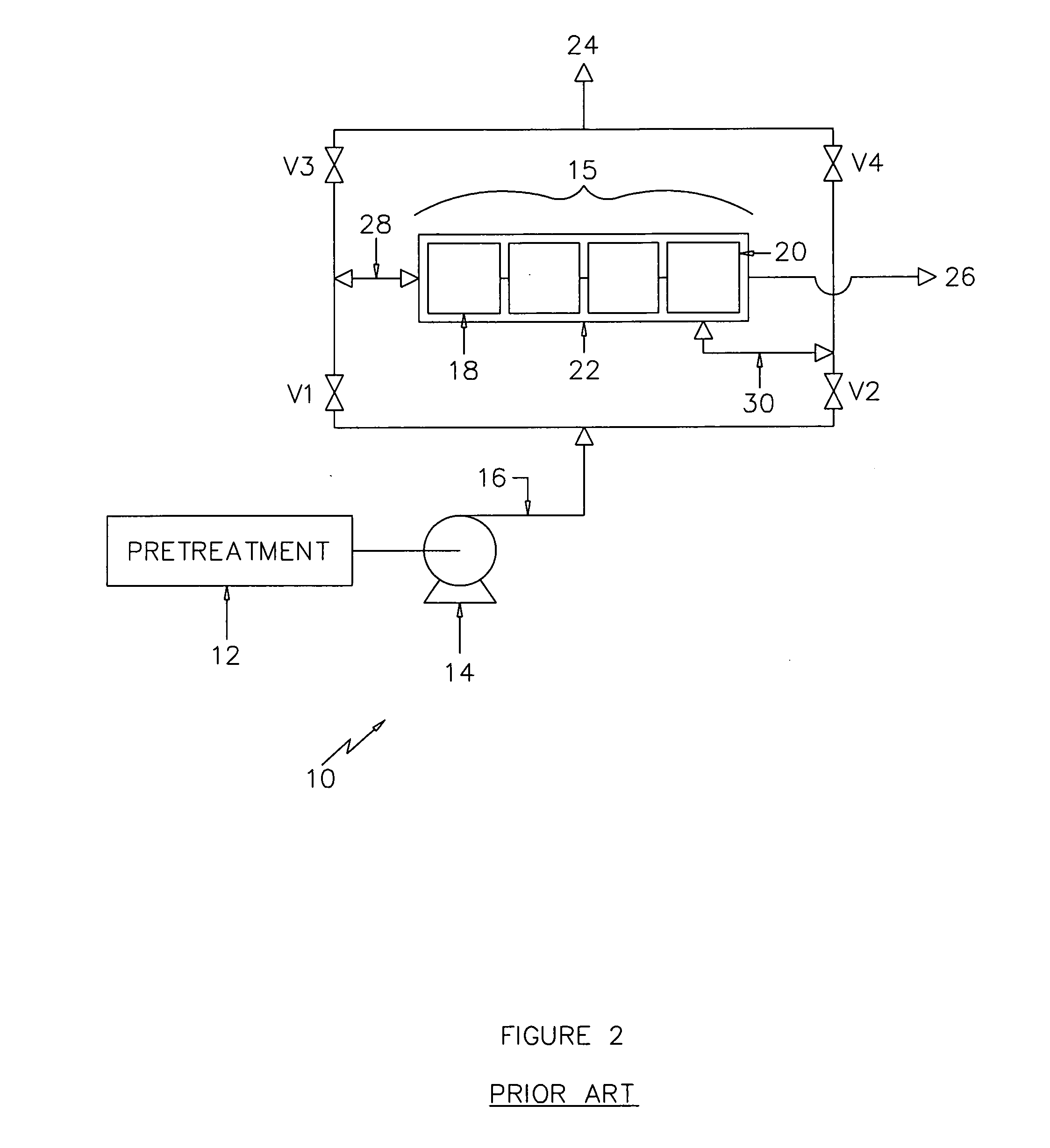
[0015]Referring first to FIG. 1, which depicts a reverse osmosis system 10 for filtering water in accordance with the prior art. Pretreated water 12 is supplied to a traditional liquid pump 14 where the pressure of the flow is increased accordingly. In the traditional reverse osmosis membrane array 15, the flow is uni-directional whereby high pressure saline liquid 16 enters the membrane array 15 disposed in a pressure vessel 22, and the first membrane element 18 of each pressure vessel 22 and then the next filter element such that at the point where the flow exits the array 15 from the last membrane element 20 the discharge flow has been converted from saline water 16 to very saline water 24, and a fresh water flow 26 has also been established. Because the flow passages of membrane elements are small, the first element 18 in the pressure vessel 22 is typically subject to more foulants that have survived the pretreatment process 12 than the last membrane element 20. Over time, the m...


PUM

PropertyMeasurementUnit
Pressureaaaaaaaaaa
Flow rateaaaaaaaaaa

Abstract

An apparatus and method for reversing the flow in a reverse osmosis system is described utilizing a single unitary valve. The improved system and method provides a means to reduce operating costs, maintenance and down time associated with a reverse osmosis system by providing a reliable and robust means to reverse the flow of fluid thereby flushing filter membranes.

Description

BACKGROUND OF THE INVENTION[0001]This invention relates generally to fluid treatment systems, and more particularly to a system and method for the continuous cleansing of reverse osmosis membranes contained within the system.SUMMARY OF THE INVENTION[0002]The reverse osmosis membrane is well suited to, and accepted for, purifying a variety of liquids, including sea water, ground water, and the like. However, the input surface of the membrane against which the pressurized input fluid to be purified is forced against and through becomes clogged of solid materials which have been filtered out to produce product liquid. As the deposit on the input surface of the membrane increase, efficiency of the membrane decreases rapidly.[0003]A number of U.S. patents attempt to address the issue of cleansing of the filter or reverse osmosis membrane either during use or in conjunction with the interruption of the purifying process. However, none of these disclose the present system or method, nor do...

Claims


Application Information

Patent Timeline
IPC IPC(8): B01D65/02F16K1/00
CPCB01D65/02B01D61/025B01D2313/18F16K11/07C02F1/441C02F2303/16B01D2321/02
Inventor SHUMWAY, SCOTT
Owner SHUMWAY SCOTT
Why Eureka
Try Eureka