

Control device of multi-phase converter and power supply system
- Summary
- Abstract
- Description
- Claims
- Application Information
AI Technical Summary
Benefits of technology
Problems solved by technology
Method used
Image

Examples
Embodiment Construction
Schematic Configuration of Fuel Cell System
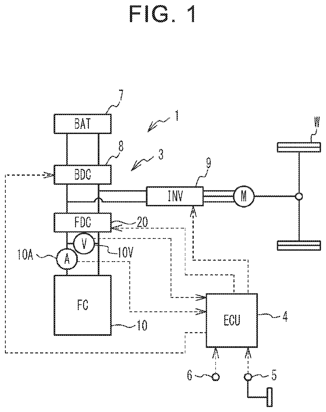
[0025]FIG. 1 is a configuration diagram of a fuel cell system 1 mounted on a vehicle. The fuel cell system 1 includes a power control system 3, an electronic control unit (ECU) 4, a secondary battery (hereinafter referred to as “BAT”) 7, and a fuel cell stack (hereinafter referred to as “FC”) 10. The power control system 3 includes a battery converter (hereinafter referred to as “BDC”) 8, an inverter (hereinafter referred to as “INV”) 9, and a boost converter (hereinafter referred to as “FDC”) 20. Although not shown in FIG. 1, the fuel cell system 1 includes an oxidant gas supply system and a fuel gas supply system that supply an oxidant gas and a fuel gas to the FC 10, respectively. Further, the vehicle is equipped with a traction motor M, wheels W, an accelerator operation amount sensor 5, and an ignition switch 6.
[0026]The FC 10 is supplied with the fuel gas and the oxidant gas to generate electric power. The FC 10 is formed by stacking ...
PUM
 Abstract
Description
Claims
Application Information