Electric power tool

Active Publication Date: 2013-05-09
MAKITA CORP
View PDF1 Cites 4 Cited by
  • Summary
  • Abstract
  • Description
  • Claims
  • Application Information

AI Technical Summary

Benefits of technology

[0009]According to the first aspect of the present invention, when the toggle switch is attached, the lever can always be inserted between the engagement portions regardless of the position of the lever. Therefore, adjusting the lever to the OFF position becomes unnecessary, and high installation efficiency is achieved.
[0010]According to the second aspect of the present i

Problems solved by technology

However, when the switch lever is biased toward an OFF position by a coil spring or the like, the toggle switch cannot be attached, wit

Method used


Image

  • Electric power tool
  • Electric power tool
  • Electric power tool

Examples


Example

[0017]In the following, an embodiment of the present invention will be described based on the drawings.

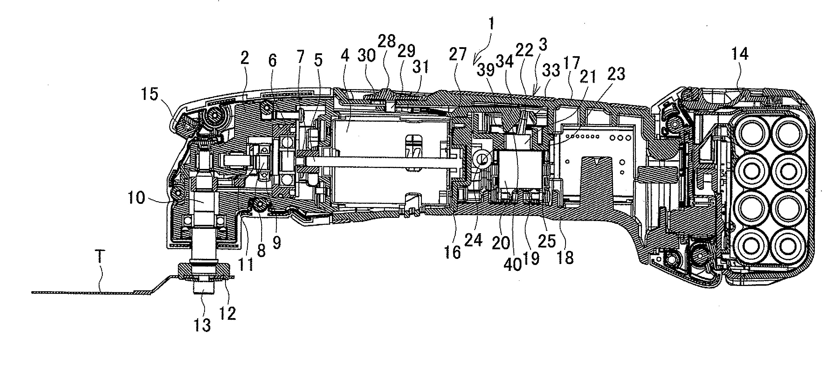
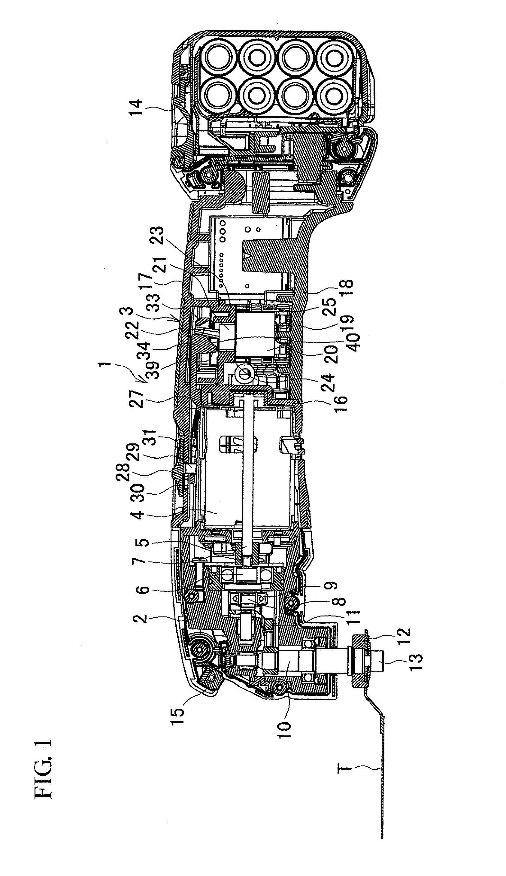
[0018]FIG. 1 is a longitudinal sectional view of a reciprocating tool as an exemplary electric power tool. A reciprocating tool 1 includes a spindle 10 protruded downward from a front housing 2 on a front side (which is the left side in FIG. 1). The spindle 10 is reciprocally rotated from side to side at a prescribed angle. A motor 4 is accommodated in a tubular motor housing 3 that is connected to the back of the front housing 2. An output shaft 5 of the motor 4 is connected, through a coupling 7, to an intermediate shaft 6 that is pivotally supported in the front housing 2 so as to be concentric with the output shaft 5. An eccentric shaft portion 8 provided with a bearing 9 on the outer peripheral surface thereof is formed at an intermediate portion of the intermediate shaft 6. A swinging member 11 that has left and right rear ends extending to the left and right outer sides of t...


PUM


Abstract

A reciprocating tool includes a toggle switch that is turned on or off by tilting a lever, and a switch lever in a motor housing. The switch lever includes an engagement frame into which the lever is inserted, and can slide in a tilting direction. The switch lever is slid to tilt the lever to an ON position or an OFF position through a sliding operation of the switch lever from the outside. An engagement portion of the switch lever on a side closer to the ON position of the lever is provided with a slanted guide surface that guides the lever in the ON position to the OFF position when the toggle switch is attached into an upper housing having the switch lever attached thereto.

Description

BACKGROUND OF THE INVENTION[0001]This application claims the benefit of Japanese Patent Application Number 2011-244773 filed on Nov. 8, 2011, the entirety of which is incorporated by reference.TECHNICAL FIELD[0002]The present invention relates to an electric power tool in which a toggle switch (also called a “snap switch”) accommodated in a housing is turned on or off through a sliding operation of a switch lever.BACKGROUND ART[0003]There are known electric power tools such as sanders that employ a toggle switch as a switch for opening and closing a driving circuit for a motor. The toggle switch is switched on or off by tilting a lever of the toggle switch through a sliding operation of a switch lever provided in a housing of the electric power tool (see, for example, Japanese Patent Application Publication No. 2002-270066 (JP 2002-270066 A)).[0004]To attach this toggle switch to the housing, first, the switch lever is attached to the housing, and then the lever of the toggle switch...

Claims


Application Information

Patent Timeline
IPC IPC(8): H01H23/24
CPCH01H15/102H01H15/107B25F5/02
Inventor MIZUTANI, AKIRAYONEYAMA, TATSUYA
Owner MAKITA CORP
Why Eureka
Try Eureka