Single-hole type heat exchanger
A technology for heat exchangers and heat exchange cores, applied in the directions of heat exchanger sealing devices, heat exchange equipment, heat exchanger shells, etc., can solve the problems of low installation efficiency, poor waterproofness, and low heat exchange efficiency of heat exchangers, etc. Achieve the effect of improving sealing, improving heat exchange efficiency, and improving installation efficiency
- Summary
- Abstract
- Description
- Claims
- Application Information
AI Technical Summary
Problems solved by technology
Method used
Image

Examples
Embodiment 1
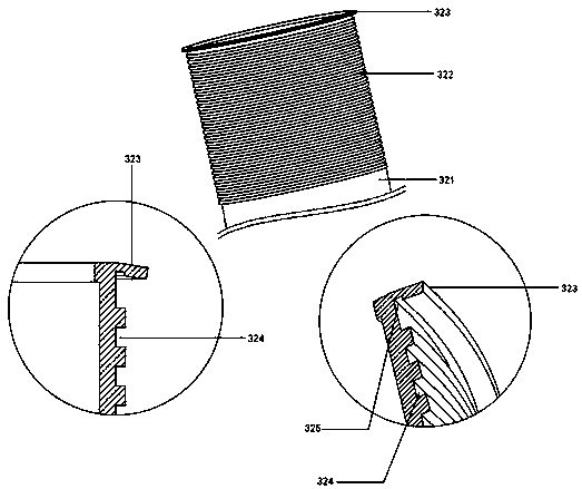
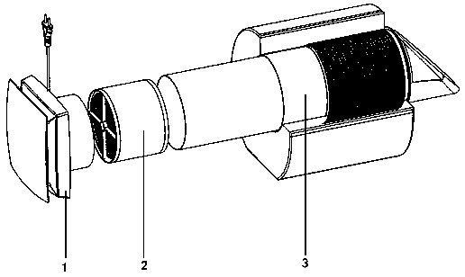
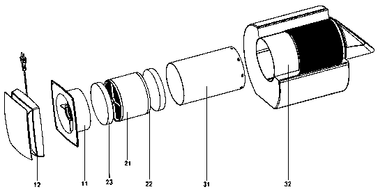
[0029] refer to Figure 1-3 As shown, a single-hole heat exchanger using a foam heat exchange core includes an exhaust fan assembly 1, a heat exchange core assembly 2 connected to the exhaust fan assembly 1, and a heat exchange core assembly 2 Connected wall exhaust pipe assembly 3, the exhaust fan assembly 1 includes a motor bracket exhaust pipe 11, and an exhaust fan front cover 12 installed on the front of the motor bracket exhaust pipe 11, the heat exchange core The assembly 2 includes a heat exchange core 21, a fixed support 22 arranged at the rear of the heat exchange core 21, and a primary filter 23 arranged at the front of the heat exchange core 21 and the rear of the fixed support 22. The wall-through exhaust pipe assembly 3 includes a heat exchange core exhaust pipe 31, and a waterproof silicone sleeve 32 that is inserted outside the heat exchange core exhaust pipe 31 and installed in the wall. The assembly 2 and the exhaust pipe 11 of the motor bracket are loaded i...
Embodiment 2
[0034] refer to Figure 1-3 As shown, a single-hole heat exchanger using a ceramic integrated heat exchange core includes an exhaust fan assembly 1, a heat exchange core assembly 2 connected to the exhaust fan assembly 1, and a heat exchange core assembly 2 connected to the heat exchange core The through-wall exhaust pipe assembly 3 connected to the assembly 2, the exhaust fan assembly 1 includes a motor bracket exhaust pipe 11, and an exhaust fan front cover 12 installed on the front of the motor bracket exhaust pipe 11, the heat The exchange core assembly 2 includes a heat exchange core 21, a fixed support 22 arranged at the rear of the heat exchange core 21, and a primary filter 23 arranged at the front of the heat exchange core 21 and the rear of the fixed support 22, The wall-through exhaust pipe assembly 3 includes a heat exchange core exhaust pipe 31, and a waterproof silicone sleeve 32 inserted outside the heat exchange core exhaust pipe 31 and installed in the wall. ...
Embodiment 3
[0039] refer to Figure 1-3 As shown, a single-hole heat exchanger using a ceramic split heat exchange core includes an exhaust fan assembly 1, a heat exchange core assembly 2 connected to the exhaust fan assembly 1, and a heat exchange core assembly 2 connected to the heat exchange core The through-wall exhaust pipe assembly 3 connected to the assembly 2, the exhaust fan assembly 1 includes a motor bracket exhaust pipe 11, and an exhaust fan front cover 12 installed on the front of the motor bracket exhaust pipe 11, the heat The exchange core assembly 2 includes a heat exchange core 21, a fixed support 22 arranged at the rear of the heat exchange core 21, and a primary filter 23 arranged at the front of the heat exchange core 21 and the rear of the fixed support 22, The wall-through exhaust pipe assembly 3 includes a heat exchange core exhaust pipe 31, and a waterproof silicone sleeve 32 inserted outside the heat exchange core exhaust pipe 31 and installed in the wall. The e...
PUM
 Abstract
Description
Claims
Application Information