However, fire accidents caused by such appliances have also become an issue.
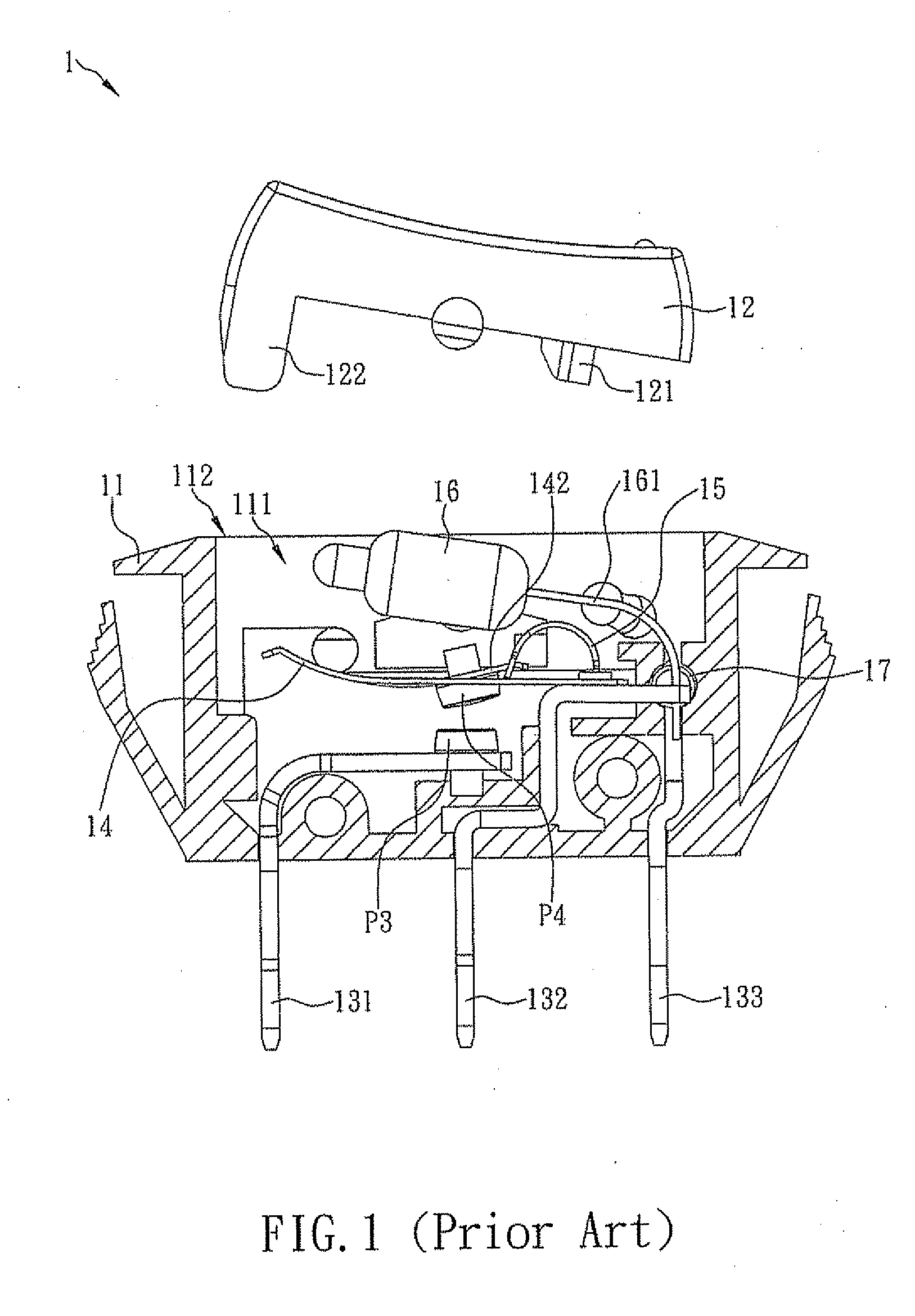
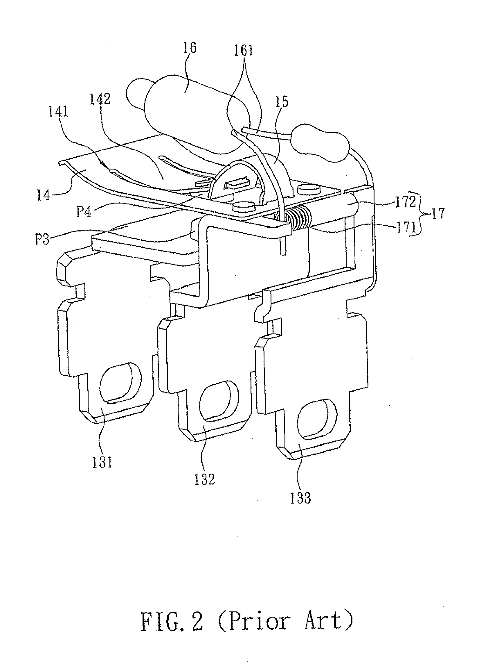
(1) As the light-emitting unit 16 is configured to have one
electrode 161 clamped between the third conductive plate 133 and the inner wall of the housing 11 and the other
electrode 161 clamped between the second conductive plate 132 and the spring 171, the
assembly process must be conducted slowly and carefully to ensure proper
electrical connection between the light-emitting unit 16, the second conductive plate 132, and the third conductive plate 133. Besides, an
assembly worker often has to move several components in order to install one, thus lowering production efficiency.
(2) The foregoing
assembly process cannot be done other than manually, so the quality of assembly depends mainly on the assembly workers' experience. To achieve a high
yield rate, a manufacturer must take considerable time training the assembly workers, which nevertheless results in high labor costs.
(3) Given the current design trend of the power switch 1 toward increased compactness, the
interior space of the housing 11 is very limited. Because of that, the electrodes 161 of the light-emitting unit 16 are often bent to save space. However, if the electrodes 161 are bent so much that they contact with the C-shaped spring 15, short circuits will occur. To prevent such short circuits, the electrodes 161 must be parted during assembly to avoid contact with the C-shaped spring 15, and this explains why the adjustment of the electrodes 161 always takes a lot of time and effort. The manual adjustment also hinders automated installation of the light-emitting unit 16 and compromises the
yield rate of the power switch 1. Moreover, the light-emitting unit 16 tends to shake slightly when the key 12 is moved back and forth. As time goes on, the accumulated effect of such slight shakes may bring the electrodes 161 closer to, or even into contact with, the C-shaped spring 15, thereby causing dangerous short circuits.
(4) The second conductive plate 132 must be bent several times so as for its top end to serve as a supporting surface for the thermally actuated
metal plate 14, and for its bottom end to extend out of the housing 11 and be adequately spaced from the first and the third conductive plates 131, 133. This bent structure of the second conductive plate 132, however, requires the use of more material than a straight structure and incurs higher material costs. Additionally, as the lower bent portion of the second conductive plate 132 is adjacent to the top end of the first conductive plate 131, the first conductive plate 131, if tilted when installed, is very likely to contact with the second conductive plates 132, thus rendering the power switch 1 useless. Furthermore, if the power switch 1 is used in a circuit configured for a large current, an
electric arc may take place between the first and the second conductive plates 131, 132 should the lower bent portion of the second conductive plate 132 be too close to the first conductive plate 131. Such electric arcs are severe safety hazards because they not only can damage the power switch 1 but also may cause fire accidents.
(1) Referring to FIG. 3, the power switch 2 has a light-emitting unit 26 whose two electrodes 261 are respectively clamped between a second conductive plate 232 and the inner wall of a housing 21 and between a third conductive plate 233 and the inner wall of the housing 21. Therefore, during the manufacturing process, an assembly worker must place the light-emitting unit 26 in the housing 21 and then insert the electrodes 261 in place while bending the electrodes 261 carefully. After that, the second conductive plate 232 and the third conductive plate 233 are assembled to the housing 21. In particular, the assembly worker must grip the free end of each
electrode 261 and
route the electrodes 261 below the second and the third conductive plates 232, 233 respectively, so as to ensure that the electrodes 261 are held in place by the two conductive plates 232, 233 respectively. If the second conductive plate 232 or the third conductive plate 233, once assembled to the housing 21, fails to hold the corresponding electrode 261 in position, the assembly worker must detach the conductive plate in question from the housing 21 and install it again. The detachment and reinstallation process not only lowers production efficiency but also may damage the components involved, thus incurring additional costs.
(2) As the key 22 relies on the push / pull bar 25 to drive the thermally actuated metal plate 24 and thereby connect or separate the first and the second contacts P5, P6, the distance between the two ends of the push / pull bar 25 is crucial to the operation of the switch 2. If the distance is too great, the push / pull bar 25 will have problem pulling the thermally actuated metal plate 24; as a result, the second contact P6 will never contact with the first contact P5. If the distance between the two ends of the push / pull bar 25 is too small, the push / pull bar 25 cannot push the thermally actuated metal plate 24 properly, and because of that, the second contact P6 will not separate from the first contact P5. Since the push / pull bar 25 is a slender and hence rather fragile metal rod, it cannot be installed by an automated process. The assembly worker must take extra care in order not to bend the push / pull bar 25; otherwise, the distance between the two ends of the push / pull bar 25 may be altered, which is detrimental to the function of the switch 2.
(3) The assembly process described above must be carried out by hand and therefore relies heavily on the assembly workers' experience. In order to increase
yield rate, a manufacturer must spend a lot of time training the assembly workers, and yet high labor costs ensue.
(4) The second conductive plate 232 must be bent several times so that its top end provides a supporting surface for the thermally actuated metal plate 24 and its bottom end extends out of the housing 21 and is properly spaced from the first and the third conductive plates 231, 233. This bent structure, however, increases the material required for making the second conductive plate 232 and thus incurs a high production cost.
The various conventional power switches on the market, though different in design, have more or less the same drawbacks that make automated production impossible; consequently, the burden of high labor costs cannot be relieved from the manufacturers' shoulders.
The soaring prices of metals also contribute to high material costs.
More importantly, the conventional power switches have safety concerns that have yet to be properly addressed.
Hence, it is a pressing issue for power switch designers and manufacturers to simplify the overall design and components of a power switch so that a light-emitting unit can be easily installed in the power switch by an automated process, thus not only reducing the labor and material costs of the power switch, but also preventing short circuits which may otherwise occur if the two electrodes of the light-emitting unit contact with a C-shaped spring.

