Medical waste disposal apparatus

a technology of medical waste and disposal apparatus, which is applied in the field of medical waste disposal apparatus, can solve the problems of saving operator time and improbable incorrect installation

Active Publication Date: 2013-05-09
CATILINA NOMINEES PTY LTD
View PDF11 Cites 18 Cited by
  • Summary
  • Abstract
  • Description
  • Claims
  • Application Information

AI Technical Summary

Benefits of technology

[0007]According to the present invention there is provided a trolley for a container for medical waste, the container having a receptacle for receiving medical waste and a lid for sealing the receptacle, the lid being pivotable between an open position and a closed position, the lid and receptacle being shaped so that an undersurface portion of the lid is accessible when the lid is in the closed position, the trolley including a retainer for retaining the container on the trolley, and a member having a lid engaging portion, the member being operable so that the lid engaging portion engages the undersurface portion of the lid and pivots the lid from the closed position to the open position, wherein the retainer and member are relatively located such that when the container is installed on the trolley and retained by the retainer, the lid engaging portion is positioned adjacent the undersurface portion of the lid without requiring manual manipulation of the member or lid.
[0008]The container is thus easily installed onto the trolley ready for use. The relative location of the retainer and member mean that when the container is installed on the trolley by an operator, no hooking or other manipulation of the member or lid by an individual for the member and lid to engage or be in contact for the member to be able to open the lid is required. This saves the operator time and makes incorrect installation unlikely. Also, as the lid engaging portion engages an undersurface portion of the lid that is accessible when the lid is in the closed position, the member does not interfere with a seal between the lid and receptacle of the container.
[0009]The member may be a lever, providing a simple means of operation. The lever, for example, may pivot in a plane with the lid engaging portion extending transverse to the plane. Alternatively, the member may be a rod that pushes the undersurface portion from below. A further alternative may have the lever including a pair of arms locatable on opposing sides of the lid to lift underside portions located on both sides of the lid.
[0010]The retainer may be shaped to allow the container to be installed downwards on the trolley, for example it may be a bracket. Further, the lid engaging portion may be positioned to engage an undersurface portion on a side of the lid. These features in combination allow easy installation of the container as the lid engaging portion does not interfere with the container during downwards installation. As an additional feature, the bracket may have a tongue to prevent over-pivoting of the lid.
[0011]The member may be operable by a foot pedal for ease of opening the container. The pedal may be biased so that the member allows the lid to return to the closed position (for example due to the weight of the lid). Where the member is a lever, a cable may extend between the foot pedal and the lever to allow operation of the member. Alternatively a linkage may be provided between the pedal and the lever. The linkage may be in the form of push rods and a further lever. These preferred embodiments provides a simple robust operation.
[0015]The medical waste containers are maintained separated from each other to prevent them rubbing together as they are being transported by the cart which could damage their appearance. Commercially it is desirable that the recyclable containers remain or be kept in as pristine condition as possible. If such containers receive cosmetic damage, they are typically buffed or polished to restore their pristine appearance. Keeping the recyclable medical waste containers separated whilst transporting them largely avoids the need for them to be buffed or polished and thus saves costs.

Problems solved by technology

This saves the operator time and makes incorrect installation unlikely.

Method used


Image

  • Medical waste disposal apparatus
  • Medical waste disposal apparatus
  • Medical waste disposal apparatus

Examples


Embodiment Construction

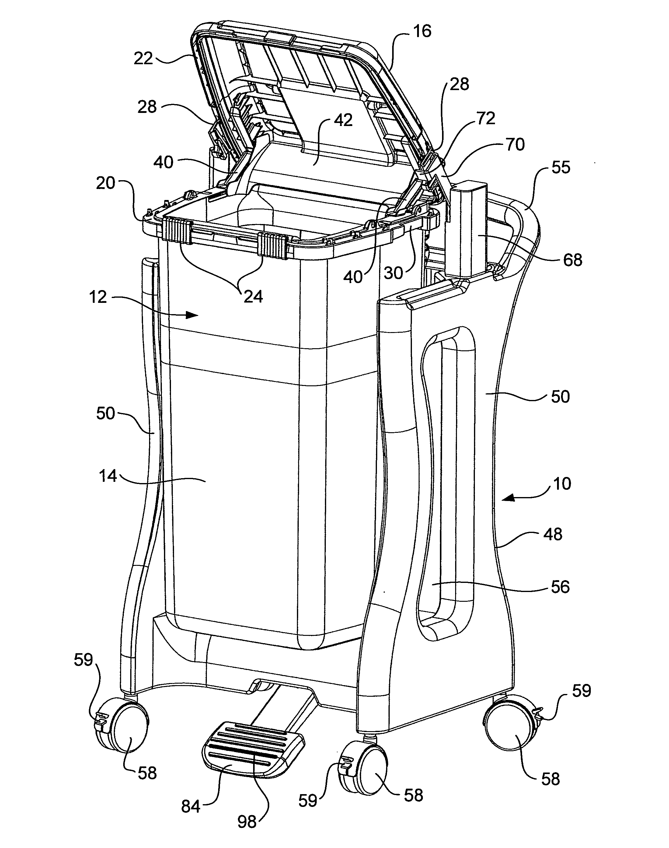
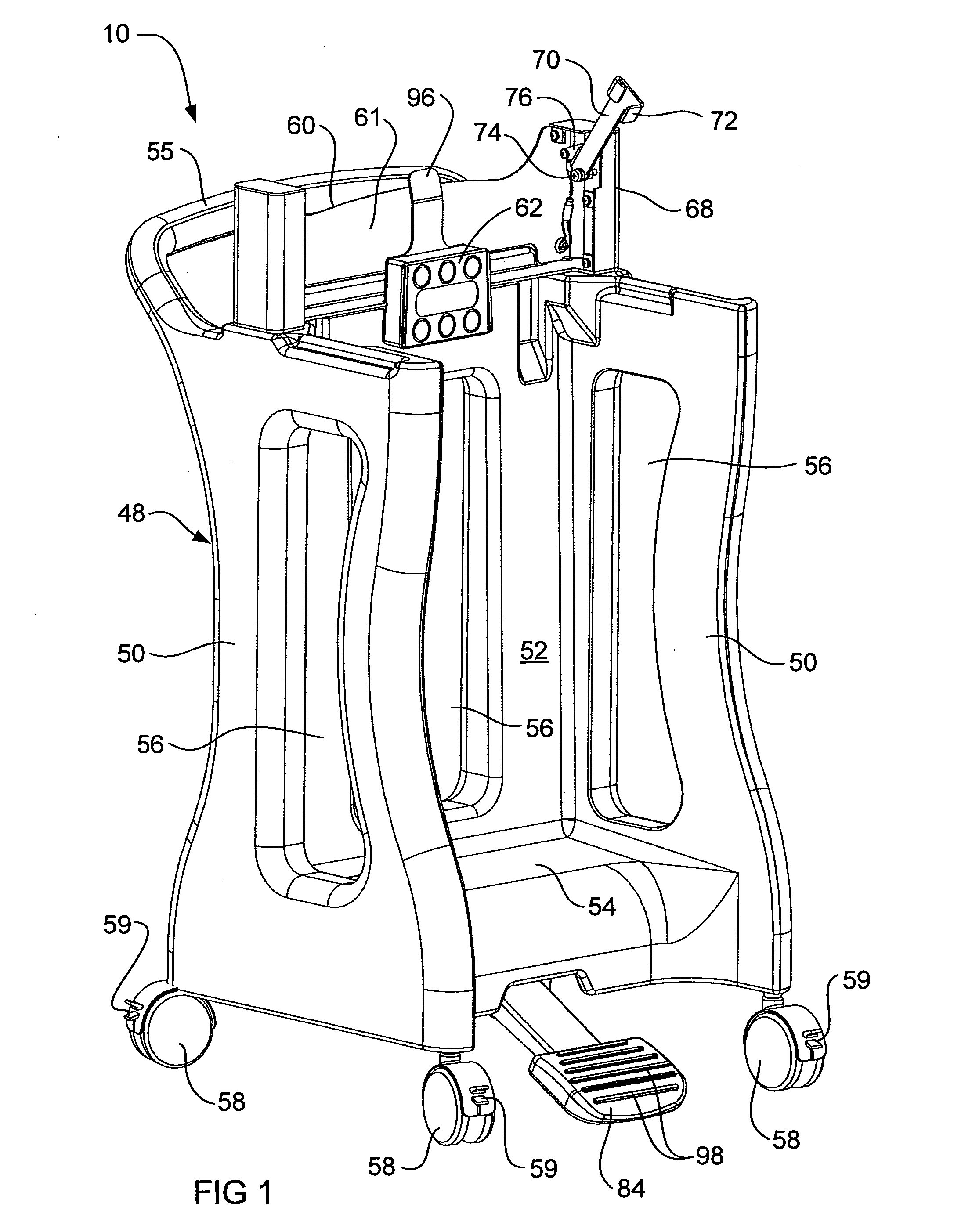
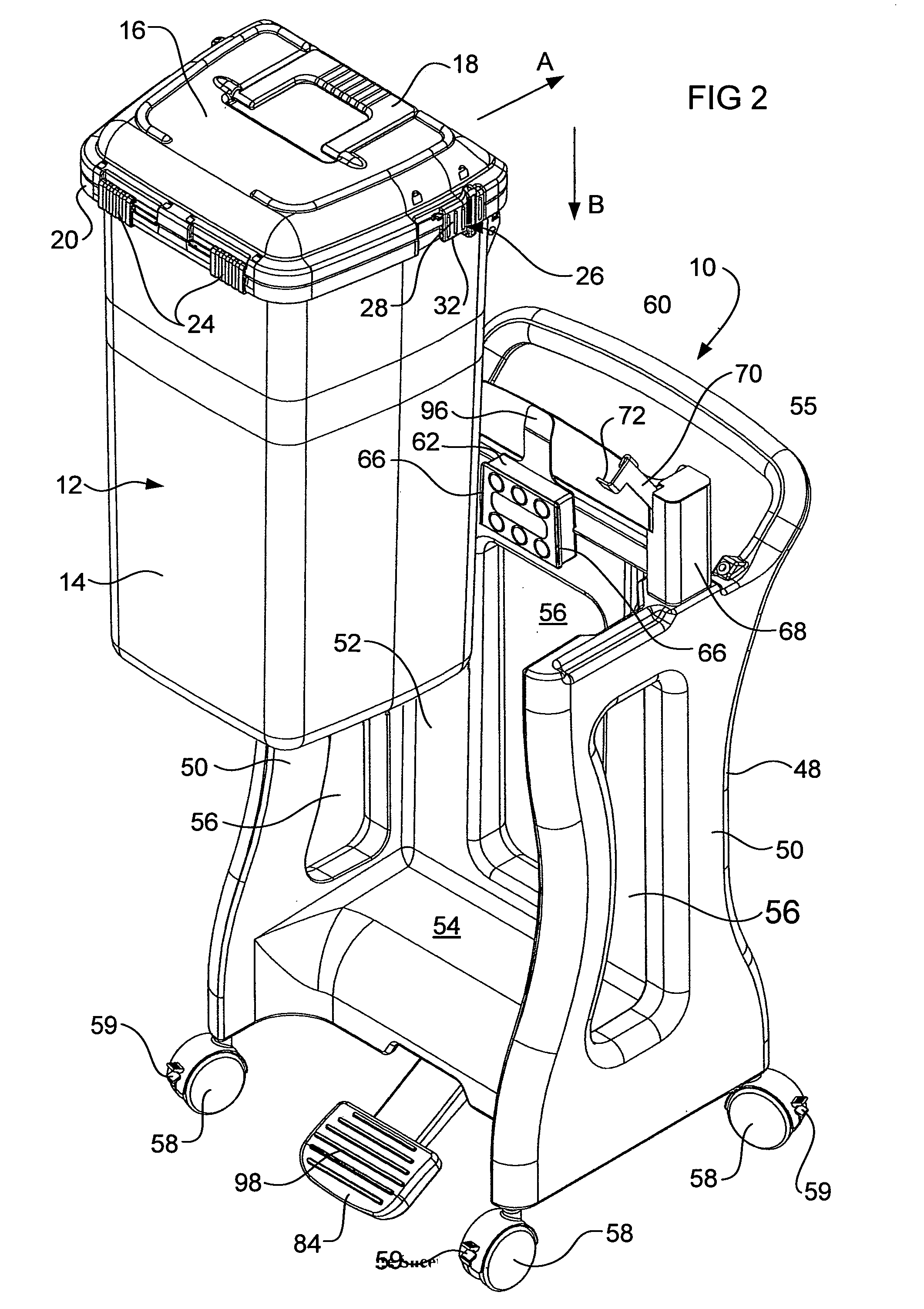
[0029]With reference to FIGS. 1-4, a trolley 10 may be used to hold a recyclable container 12 for medical waste that is generated in a hospital or other medical facility, such as an operating theatre. The container 12 comprises a receptacle 14 with a pivotable lid 16 having a handle 18. The receptacle 14 includes a top rim 20 having a flat upper surface against which a seal 22 (see FIG. 4) in the periphery of the lid 16 seals when the lid 16 is held in its closed position on the receptacle rim 20. The lid 16 may be held closed on the rim 20 by two slidable latches 24 carried by the receptacle's rim 20. The latches 24 can be unlatched to allow the lid 16 to be pivoted to an open position. At each side of the container 12 and carried by the lid 16 is a lock 26 for locking the lid 16 to the receptacle 14. Thus when the receptacle 14 is filled (as hereinbefore defined) with medical waste, the lid 16 is latched closed by the latches 24 and then locked closed by the locks 26. Once locked,...


PUM


Abstract

The present invention relates to a trolley (10) for a medical waste container (12) for use in a medical treatment facility such as an operating theatre or other hospital or medical environment. The invention also relates to a cart (100) for transporting a collection of the medical waste containers (12) throughout the medical treatment facility.

Description

TECHNICAL FIELD[0001]The present invention relates to a trolley for a medical waste container for use in a medical treatment facility such as an operating theatre or other hospital or medical environment. The invention also relates to a cart for transporting a collection of the medical waste containers throughout the medical treatment facility.BACKGROUND[0002]Medical treatment facilities generate a lot of disposable medical waste, for example sponges, gauze, drapes, bandages etc. and sharps of various types. Such waste is usually contaminated with the blood or body fluids of a patient, which biohazards can possibly expose medical staff or other patients to infectious diseases should they accidentally come into contact with the medical waste. Thus such medical waste requires special handling immediately following its generation and continuing through to its ultimate destruction.[0003]Waste medical sharps may be disposed of separately to non-sharps medical waste into specially constru...

Claims


Application Information

Patent Timeline
Patent Type & Authority Applications(United States)
IPC IPC(8): A61G12/00A61B19/00
CPCA61B17/06133A61G12/001A61B19/0287A61B19/0288A61B2017/00973A61B2019/0209A61B2019/0221A61B2019/025B62B3/004B62B2202/20B65F1/141B65F1/1468B65F1/1615B65F1/163B65F2001/1676B65F2210/18A61B19/00A61B19/0248A61B2050/0056A61B2050/0067A61B90/00A61B50/10A61B50/13A61B50/36A61B50/362A61B2050/005B62B3/04B62B3/104
Inventor PENNINGS, BERTHART, CHRIS
Owner CATILINA NOMINEES PTY LTD
Why Eureka
Try Eureka