
Temperature compensated frequency reference comprising two MEMS oscillators

Inactive Publication Date: 2013-05-09
AALTO UNIVERSITY FOUDATION SR
View PDF7 Cites 17 Cited by
  • Summary
  • Abstract
  • Description
  • Claims
  • Application Information

AI Technical Summary

Benefits of technology

[0004]The aim of invention is to enable smaller and more cost effective frequency reference than quartz oscillator with good noise performance and good long term stability. The closest prior art is to compensate the output frequency of the synthesizer by altering the PLL division ratio to compensate the frequency error of the MEMS reference frequency. This leads to high amount of quantization noise that must be filtered out. This is often not tolerable, and reduction of frequency noise by filtering and by

Problems solved by technology

This leads to high amount of quantization noise that must be filtered out.
This is often not tolerable, and reduction of frequency noise by filtering and by using high Q tank oscillator leads to very high oper

Method used


Image

  • Temperature compensated frequency reference comprising two MEMS oscillators
  • Temperature compensated frequency reference comprising two MEMS oscillators

Examples


Example

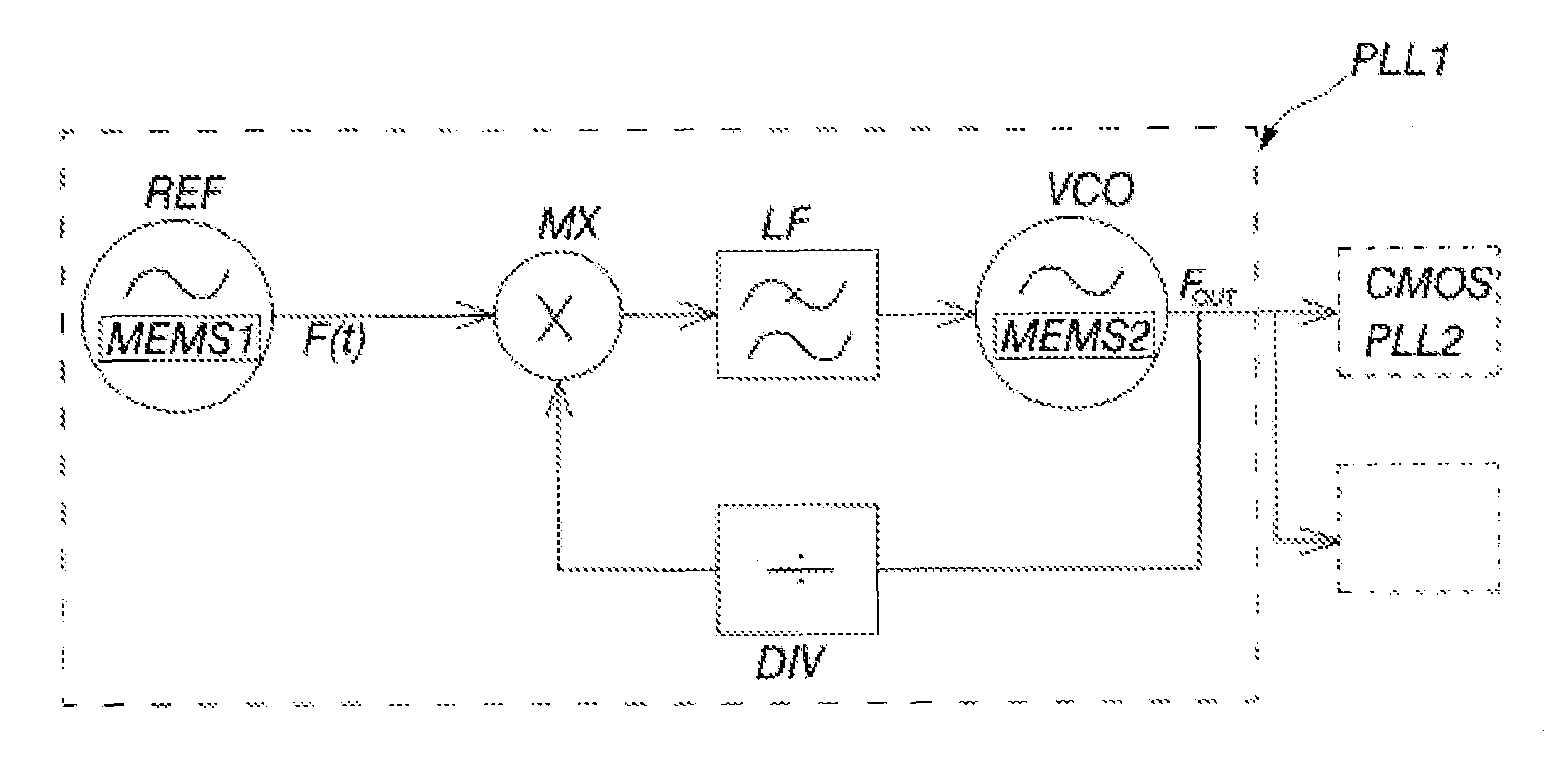
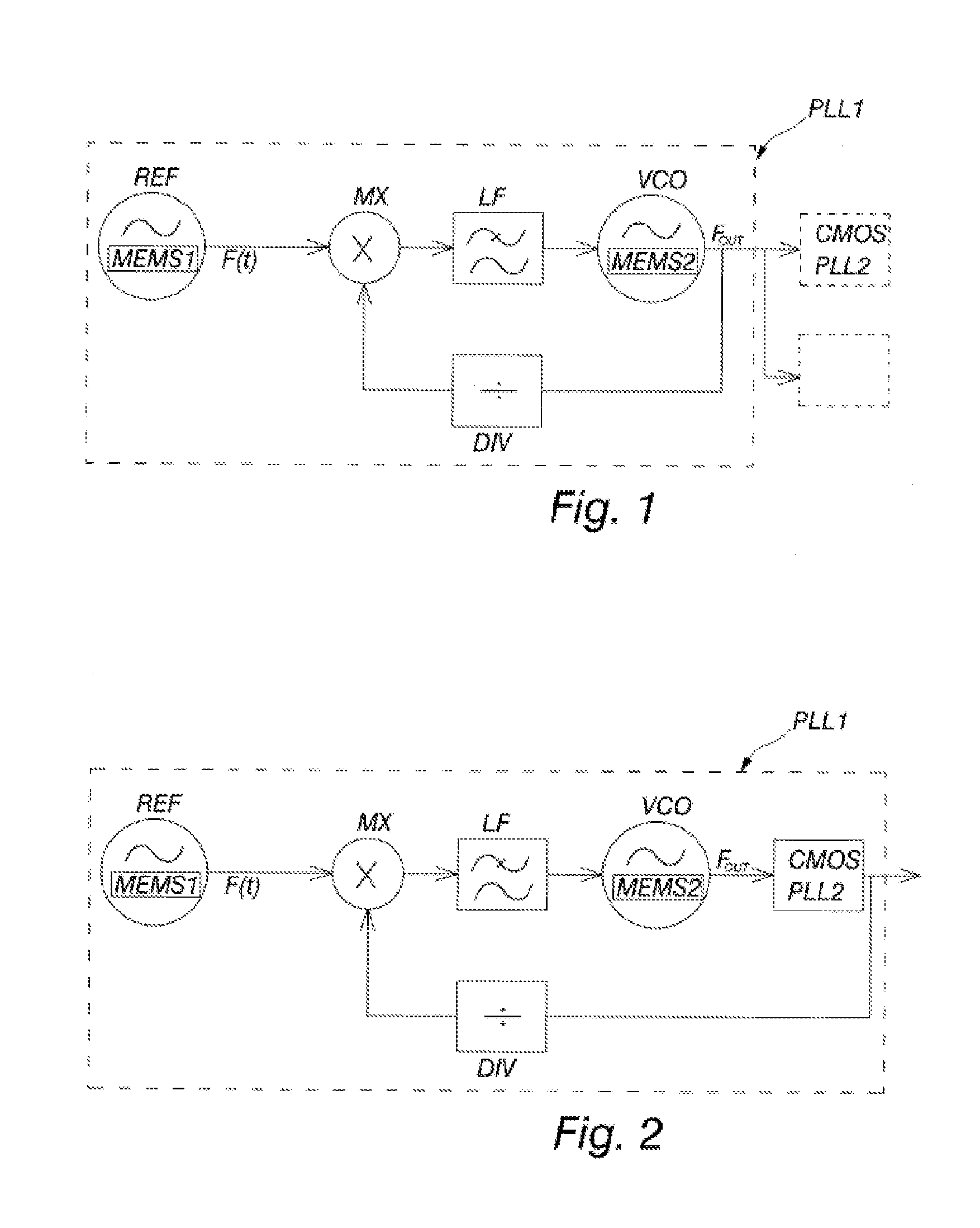
[0010]FIG. 1 presents a simplified block diagram of the PLL system according to the invention. The inventive system comprises two MEMS based oscillators, reference oscillator REF and PLL controlled oscillator VCO.

[0011]Reference oscillator REF comprises first MEMS-resonator based oscillator MEMS1. Reference oscillator generates frequency F(t) that is temperature dependent, and the temperature of the MEMS1 oscillator is measured for compensation. The temperature compensation is made by adjusting fractional division ratio of divider DIV, and the frequency correction of VCO is therefore adjusted as function of temperature. MX is multiplier (phase detector) or a phase-frequency detector, LF is loop filter. The principle of PLL is well known and not described here in detail. The invention is usable with several known variants of PLL, with both analogue and digital control of VCO and with different implementations of fractional frequency divider DIV, including sigma-delta-modulated contro...


PUM


Abstract

A temperature compensated frequency reference comprising first MEMS oscillator (MEMS1) used as frequency reference oscillator (REF) for phase locked loop, and means for temperature compensation of phase locked loop output frequency (Fout), wherein the phase locked loop comprises a second MEMS oscillator (MEMS2) used as electronically controlled oscillator (VCO) of phase locked loop.

Description

[0001]The invention relates to PLL (Phase Locked Loop) system that uses MEMS (Micro-Electro-Mechanical Systems) reference oscillator and electronically controlled MEMS oscillator for stable low noise frequency source.BACKGROUND [0002]MEMS frequency references are enabling a cheap and versatile reference frequency source to various kinds of integrated circuits. Presently the more expensive and bulky quartz references are dominant. The worst problem of MEMS oscillators is their large temperature dependency that causes a frequency error up to 0.5% within typical temperature range. The inventive solution proposed for compensating the error is a combination of electrostatic frequency control and fractional PLL. The latter involves the use of a well known PLL frequency synthesis principle and adjusting of the fractional ratio of the divider according to the temperature error of the frequency reference. Typically this is made by measuring the temperature and using some digital-signal-proce...

Claims


Application Information

Patent Timeline
IPC IPC(8): H03L7/08
CPCH03L1/02H03L7/099H03L7/08H03L7/235H03L7/23H03L7/06
Inventor AALTONEN, LASSEGRONICZ, JAKUBHALONEN, KARI
Owner AALTO UNIVERSITY FOUDATION SR
Learn More