
Thermoelectric device and method for manufacturing the same

a technology of thermoelectric devices and electrodes, which is applied in the manufacture/treatment of thermoelectric devices, thermoelectric device details, and thermoelectric device junction materials. it can solve the problems of high energy required for charging to move, poor wetting properties of thermoelectric legs and electrodes, and deformation of thermoelectric properties, so as to facilitate charge movement and reduce contact resistance

Active Publication Date: 2020-10-29
KOREA INST OF SCI & TECH
View PDF0 Cites 0 Cited by
  • Summary
  • Abstract
  • Description
  • Claims
  • Application Information

AI Technical Summary

Benefits of technology

This patent is aimed at reducing the contact resistance between a thermoelectric leg and an electrode in a thermoelectric device to improve power generation and reduce total resistance. The solution involves inserting a separate interlayer between the two materials to create a tunneling path for charge movements. This results in a higher amount of generated power and better performance of the thermoelectric device, with the added benefit of lower process costs for large-scale production.

Problems solved by technology

The thermoelectric legs and the electrodes have poor wetting properties due to the material problem, and because there is a high energy barrier between the thermoelectric legs and the electrodes, high energy is required for charges to move.
As described above, because contact resistance between the thermoelectric legs and the electrodes is high, the total internal resistance increases and the thermoelectric properties degrade, and thus an amount of power generated by the thermoelectric device reduces.

Method used


Image

  • Thermoelectric device and method for manufacturing the same
  • Thermoelectric device and method for manufacturing the same
  • Thermoelectric device and method for manufacturing the same

Examples


Embodiment Construction

[0031]Hereinafter, exemplary embodiments of the present disclosure will be described with reference to the accompanying drawings. The present disclosure is described with reference to the embodiments shown in the drawings, but this is described as an embodiment, and the technical spirit of the present disclosure and its key elements and operation are not limited thereby.

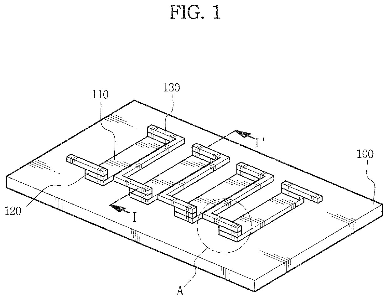
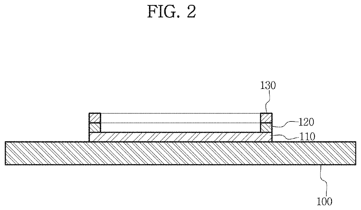
[0032]FIG. 1 is a perspective view showing the structure of a thermoelectric device according to an embodiment of the present disclosure, and FIG. 2 is a cross-sectional view taken along the line I-I′ of FIG. 1.

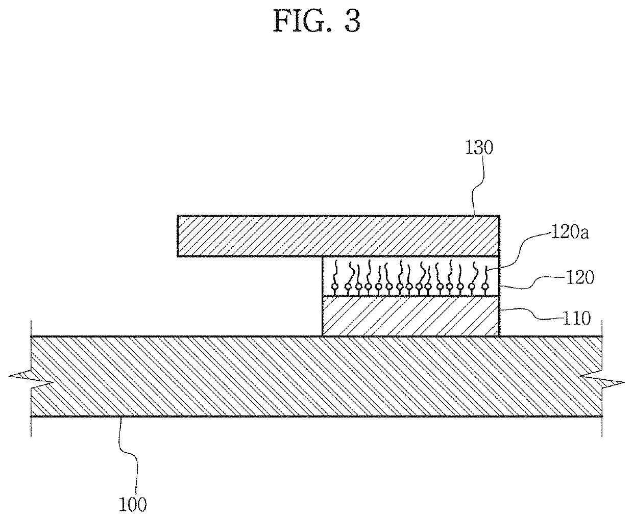
[0033]Referring to FIGS. 1 and 2, the thermoelectric device includes a substrate 100, a thermoelectric leg 110, an interlayer 120 and an electrode 130.

[0034]The substrate 100 may be an insulating substrate or a metal substrate. The insulating substrate may be an aluminum substrate or a flexible polymer resin substrate. The flexible polymer resin substrate may include various types of insulating resin materials...


PUM

PropertyMeasurementUnit
lengthaaaaaaaaaa
resistanceaaaaaaaaaa
contact resistanceaaaaaaaaaa

Abstract

Disclosed is a thermoelectric device in which a separate interlayer is inserted between a thermoelectric leg and an electrode to reduce the contact resistance between the thermoelectric leg and the electrode, so that the interlayer serves as a tunneling path between the thermoelectric leg and the electrode, facilitating the charge movements between the two materials, and the thermoelectric device according to an embodiment includes a substrate, a thermoelectric leg positioned on the substrate, an interlayer positioned on the thermoelectric leg, and including a plurality of interlayer materials chemically bonded with the thermoelectric leg, and an electrode positioned on the interlayer, and electrically connected to the thermoelectric leg.

Description

CROSS-REFERENCE TO RELATED APPLICATION[0001]This application claims priority to Korean Patent Application No. 10-2019-0049276, filed on Apr. 26, 2019, and all the benefits accruing therefrom under 35 U.S.C. § 119, the contents of which in its entirety are herein incorporated by reference.STATEMENT REGARDING SPONSORED RESEARCH[0002]This study was supported by an individual basic research project of the Ministry of Science and ICT (Development of large area wearable molybdenum disulfide photo sensor array using printing technology, Project No. 1711087699) under the superintendence of National Research Foundation of Korea.BACKGROUND1. Field[0003]The present disclosure relates to a thermoelectric device with improved properties of the device through the reduction of contact resistance and a method for manufacturing the same.2. Description of the Related Art[0004]Thermoelectric conversion refers to energy conversion between thermal energy and electrical energy. Typically, thermoelectric ...

Claims


Application Information

Patent Timeline
Patent Type & Authority Applications(United States)
IPC IPC(8): H01L35/12H01L35/34H01L35/02
CPCH01L35/12H01L35/02H01L35/34H10N10/85H10N10/80H10N10/01H10N10/856H10N10/17
Inventor CHUNG, SEUNGJUNLEE, PHILLIPPARK, MINLEE, SANG-SOOKIM, HEESUKSON, JEONG GONPARK, JONG HYUKKIM, TAE ANNHWANG, SEONGKWONJEONG, INHO
Owner KOREA INST OF SCI & TECH
Learn More