Contact mechanism and electromagnetic contactor using same
a contact mechanism and electromagnetic technology, applied in the field of contact mechanisms, can solve problems such as enlarging the entire configuration, and achieve the effect of preventing the movement of the contact and reducing the thrust of the electromagnet driving the movable conta
- Summary
- Abstract
- Description
- Claims
- Application Information
AI Technical Summary
Benefits of technology
Problems solved by technology
Method used
Image
Examples
first embodiment
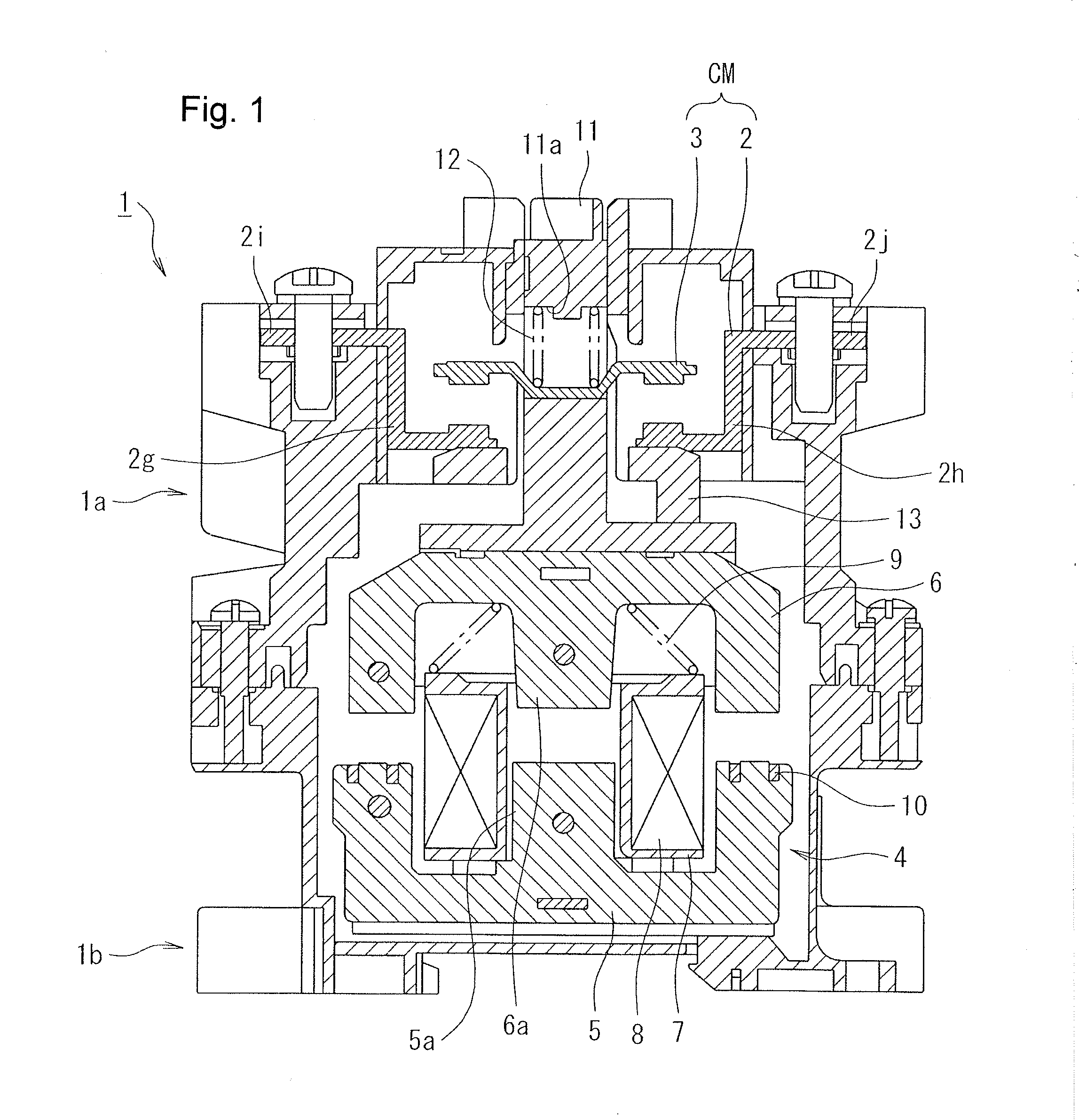
[0034]Operations of the above-described first embodiment are described next.
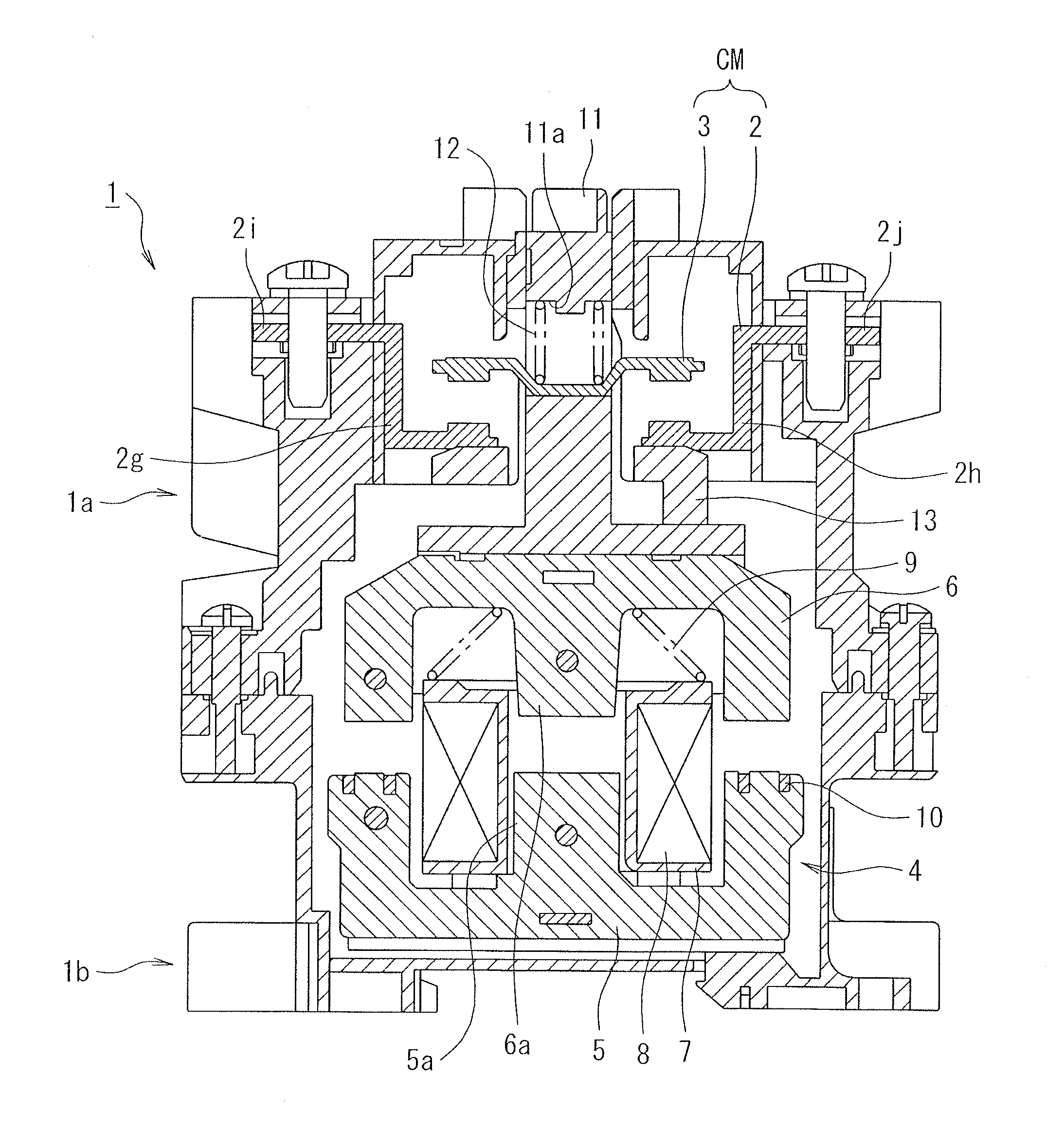
[0035]When the electromagnetic coil 8 of the operating electromagnet 4 is in a non-conductive state, no electromagnetic attracting force is generated between the fixed core 5 and the movable core 6, and, consequently, the movable core 6 is urged by the return spring 9 to move upward away from the fixed core 5. The upper end of the movable core 6 is then abutting with a stopper 13 and accordingly held at a current cutoff position.
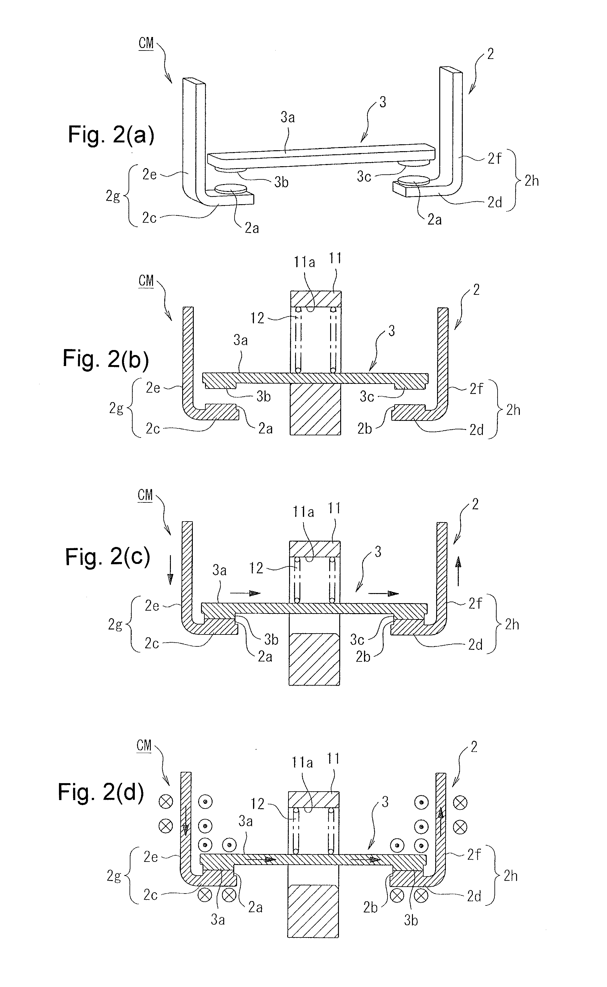
[0036]In a state in which the movable core 6 is held at the current cutoff position, the contact spring 12 brings the movable contact 3 into contact with a bottom part of the insertion hole 11a of the contact holder 11, as shown in FIG. 2(b). In such a state, the movable contact point parts 3b, 3c formed on the ends of the conductive plate 3a of the movable contact 3 separate upward from the fixed contact point parts 2a, 2b of the fixed contact 2, obtaining an opened state of the con...
second embodiment
[0043]Next, the present invention is described with reference to FIGS. 3(a)-3(c).
[0044]In the second embodiment, the Lorentz force acting against the abovementioned electromagnetic repulsion is generated on the back of the movable contact, the electromagnetic repulsion being generated with respect to the fixed contact and the movable contact.
[0045]In other words, the second embodiment has the same configuration as that of the first embodiment, except that the second embodiment has a configuration shown in FIGS. 3(a)-3(c) in which, according to the configuration of the first embodiment shown in FIG. 2(a)-2(d), the second conductive plate parts 2e, 2f of the L-shaped conductive plate parts 2g, 2h of the fixed contact 2 are bent so as to cover upper ends of the end parts of the conductive plate 3a of the movable contact 3 to form third conductive plate parts 2m, 2n parallel to the conductive plate 3a, thereby configuring U-shaped conductive parts 2o, 2p.
[0046]According to the second e...
third embodiment
[0052]Next, the present invention is described with reference to FIGS. 4(a)-4(c).
[0053]Unlike the second embodiment, the third embodiment forms U-shaped folded parts in the movable contact.
[0054]In other words, in the third embodiment, U-shaped folded parts 3h, 3i that are folded above the conductive plate 3a are formed by first conductive plate parts 3d, 3e extending upward from the ends of the conductive plate 3a of the movable contact 3 and second conductive plate parts 3f, 3g that extend inward from upper ends of the first conductive plate parts 3d, 3e, as shown in FIGS. 4(a) to 4(c). Movable contact point parts 3j, 3k are formed on lower surfaces of tip ends of the second conductive plate parts 3f, 3g of these U-shaped folded parts 3h, 3i.
[0055]Furthermore, in an opened state of the contact mechanism CM, the fixed contact 2 has L-shaped conductive plate parts 2u, 2v, which are formed by fourth conductive plate parts 2q, 2r that extend inward facing the conductive plate 3a and ...
PUM
 Abstract
Description
Claims
Application Information
 - R&D
- Intellectual Property
- Life Sciences
- Materials
- Tech Scout
- Unparalleled Data Quality
- Higher Quality Content
- 60% Fewer Hallucinations
Browse by: Latest US Patents, China's latest patents, Technical Efficacy Thesaurus, Application Domain, Technology Topic, Popular Technical Reports.
© 2025 PatSnap. All rights reserved.Legal|Privacy policy|Modern Slavery Act Transparency Statement|Sitemap|About US| Contact US: help@patsnap.com


