
Blind Spot Detection Alert System

a blind spot and alert system technology, applied in the field of detection alert system, can solve the problems of inconvenience for drivers, driver cannot pay attention to the blind spot area in the sideward and backward direction, and the driver would not be warned of the approaching object, so as to reduce the information error rate effectively and facilitate the effect of drivers

Inactive Publication Date: 2013-05-09
ALTEK AUTOTRONICS
View PDF5 Cites 22 Cited by
  • Summary
  • Abstract
  • Description
  • Claims
  • Application Information

AI Technical Summary

Benefits of technology

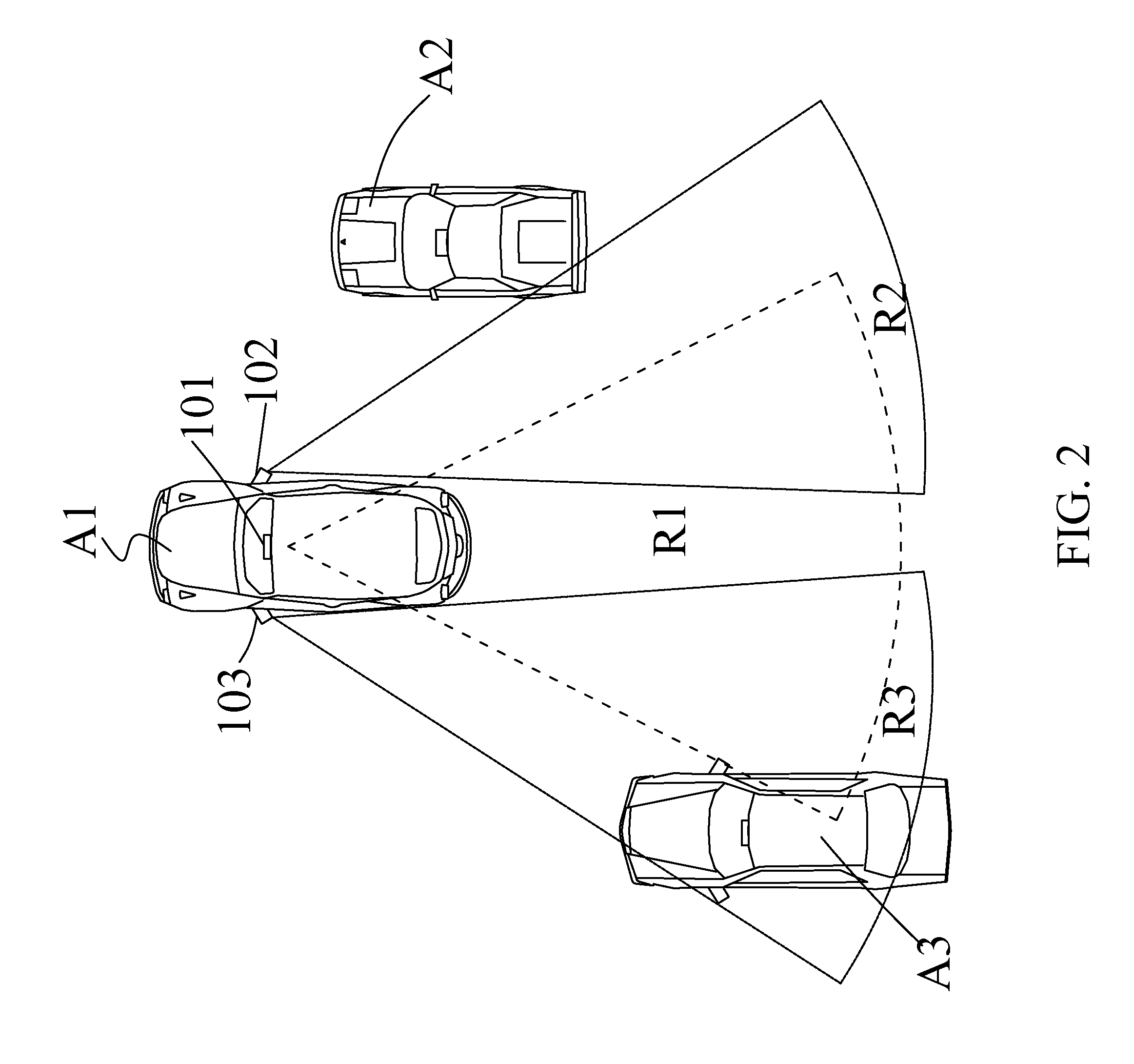
The present invention provides a blind spot detection alert system to help drivers see approaching objects in their blind spot. The system uses a first display module, second display module, or head-up display module to detect the driver's behavior or intention to obtain the distance, direction, or speed of an approaching object. This information is then used to dynamically adjust the system's algorithm, sensitivity, and computation resources to reduce information errors and improve efficiency. Additionally, the first display module and second display module can be used to categorize or divide the dynamic image to make it easier for drivers to identify approaching cars or objects in their blind spot.

Problems solved by technology

Generally speaking, when driving, a driver cannot pay attention to a blind spot area in the sideward direction and backward direction due to the structure of a vehicle body, even though the driver has used a large or wide-angle side mirror.
However, when the drivers drive the car to the left side, most drivers usually look at the left-side mirror to determine whether there is an obstacle in the blind spot area or not, but the screen on the center console cannot provide immediate information to the drivers to assure driver safety, which causing inconvenience to the drivers.
However, the driver would not be warned of the approaching object in the blind spot area through the warning effect and the distance between the approaching object in the blind spot area and the vehicle.
As a result, a comprehensive protection cannot be provided during driving, particularly when an approaching car is situated within a blind spot area.
Obviously, it is an urgent issue for designers and manufacturers to design and develop a blind spot detection alert system capable of detecting the behavior and the intention of drivers during driving, allowing drivers to be at the sight of an approaching car, and dynamically adjusting the sensitivity and computing resource.

Method used


Image

  • Blind Spot Detection Alert System
  • Blind Spot Detection Alert System
  • Blind Spot Detection Alert System

Examples


Embodiment Construction

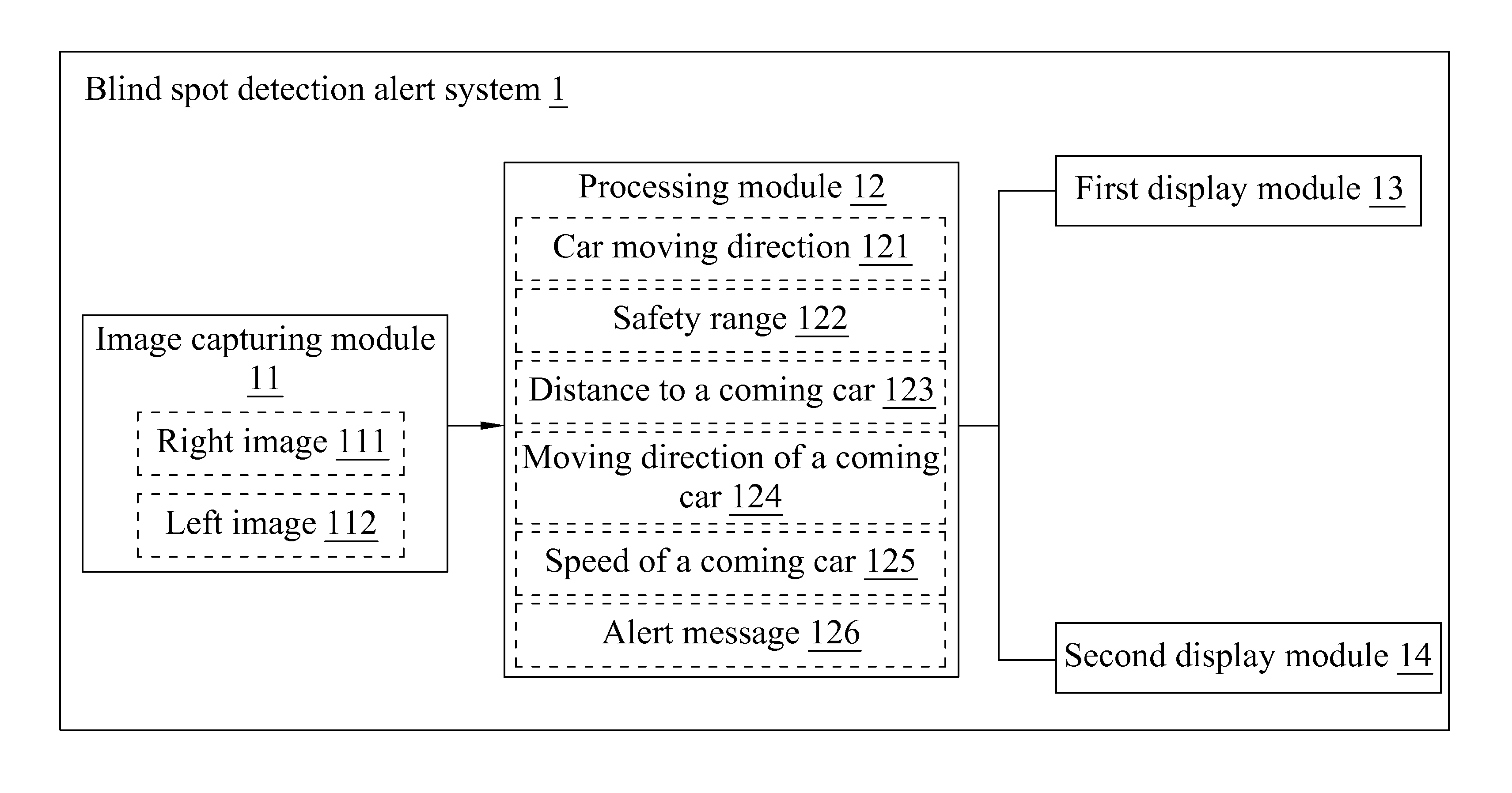
[0023]With reference to FIG. 1 for a block diagram of a blind spot detection alert system in accordance with the first preferred embodiment of the present invention, the blind spot detection alert system 1 comprises an image capturing module 11, a processing module 12, a first display module 13 and a second display module 14. Preferably, the blind spot detection alert system 1 of the present invention is installed at a car, such that a driver can definitely recognize an object approaching the blind spot, and the actual distance, direction or speed of the approaching object, and then the driver can keep distance from the approaching object. The image capturing module 11 may be a photo sensitive element such as a complementary metal oxide semiconductor (CMOS) or a charge coupled device (CCD), a lens and a lens module. The processing module 12 is electrically coupled to the image capturing module 11, and the processing module 12 may be a central processing unit (CPU) or a micro process...


PUM


Abstract

A blind spot detection alert system. The system comprises two image capturing modules, a processing module, a first display module and a second display module. The two image capturing modules capture a right image and a left image respectively. The first display module is disposed on the right of the second display module. The processing module receives the right image and the left image to analyze a car moving direction. When the processing module determines the car moving direction is a right direction, the first display module displays the right image. When the processing module determines the car moving direction is a left direction, the second display module displays the left image. The processing module calculates a distance to a coming car, a moving direction of the coming car and a speed of the coming car according to the image to get an alert message.

Description

CROSS-REFERENCE TO RELATED APPLICATION[0001]This application claims the benefit of priority to Taiwan Patent Application No. 100140949, filed on Nov. 9, 2011, in the Taiwan Intellectual Property Office, the disclosure of which is incorporated herein in its entirety by reference.BACKGROUND OF THE INVENTION[0002]1. Field of the Invention[0003]The present invention relates to a detection alert system, in particular to the blind spot alert detection system capable of detecting the behavior and the intention of a driver and observing an approaching car in a blind spot area to dynamically adjust the sensitivity and computing resource for blind spot detection.[0004]2. Description of the Related Art[0005]Generally speaking, when driving, a driver cannot pay attention to a blind spot area in the sideward direction and backward direction due to the structure of a vehicle body, even though the driver has used a large or wide-angle side mirror. Therefore, a detection system for a blind spot is ...

Claims


Application Information

Patent Timeline
IPC IPC(8): H04N7/18
CPCB60R2300/20H04N7/18B60R1/00B60R2300/70B60R1/28B60R1/26
Inventor CHIEN, CHUN-LIANGTSAI, CHIH-WOEITU, CHIH-CHENG
Owner ALTEK AUTOTRONICS
Learn More