
Vibration dumping device

a technology of vibration damping and damping ability, which is applied in the direction of slip couplings, couplings, mechanical equipment, etc., can solve the problems of degrading the damping ability and the durability of the pendulum damper, and achieve the effect of reducing the change in the order frequency of oscillating motion

Active Publication Date: 2013-05-09
TOYOTA JIDOSHA KK
View PDF1 Cites 20 Cited by
  • Summary
  • Abstract
  • Description
  • Claims
  • Application Information

AI Technical Summary

Benefits of technology

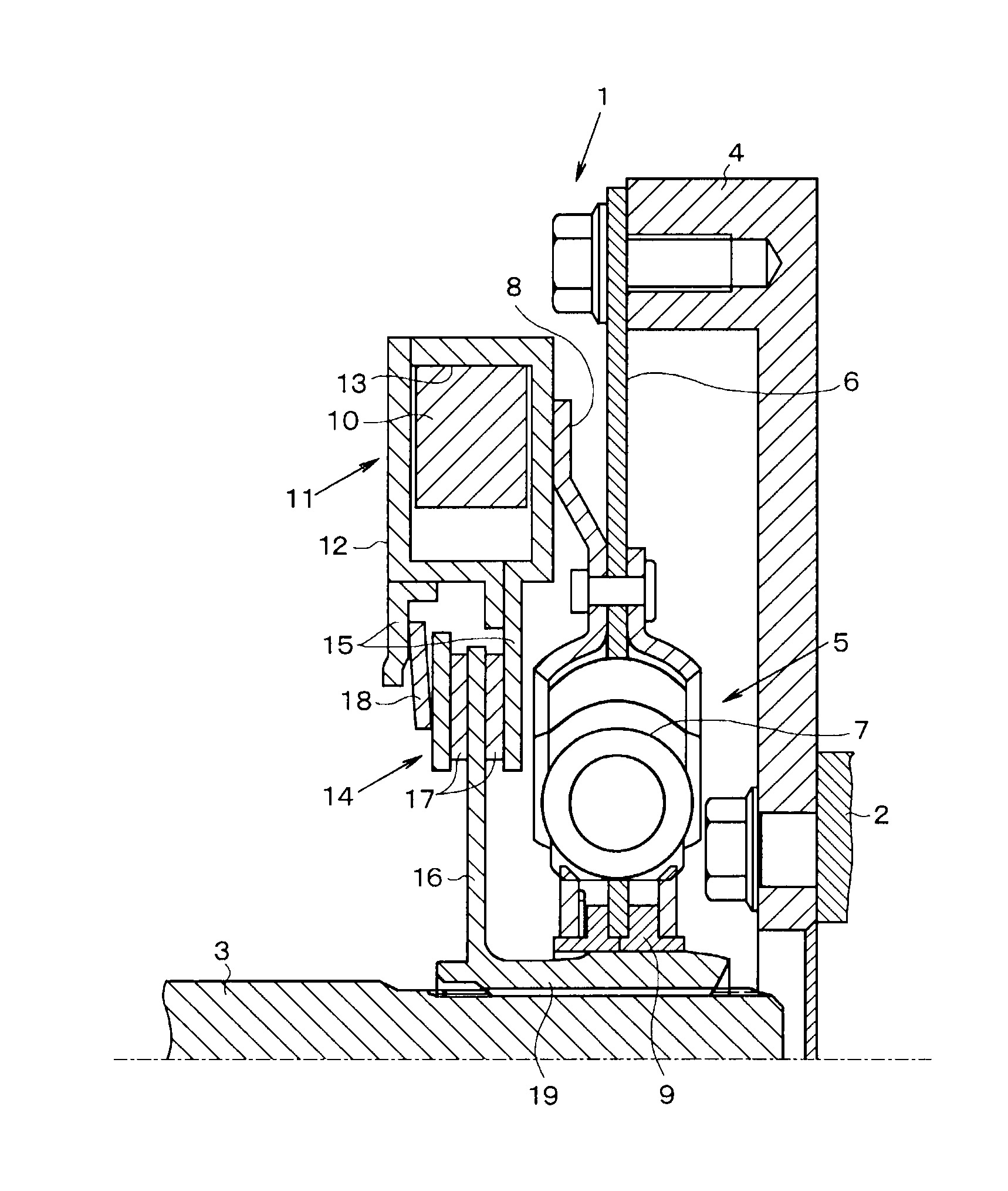
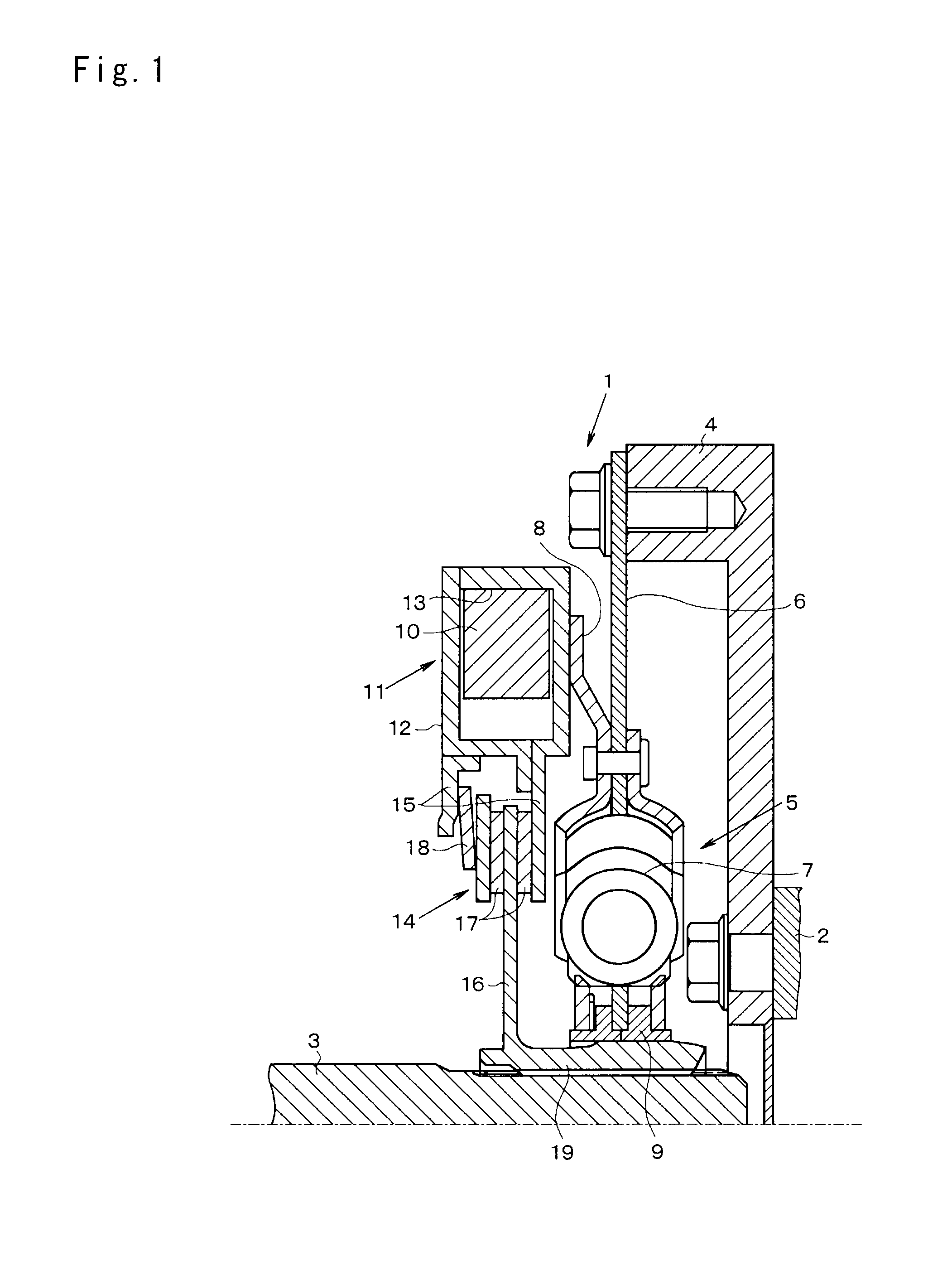
The present invention provides a vibration damping device that reduces changes in the frequency of motion caused by eccentricity of rotational centers in a vibration damping device. The device includes an inertial body, elastic damping mechanism, pendulum damping mechanism, and torque limiter mechanism. The torque limiter mechanism is connected with the pendulum damping mechanism in a power transmittable manner, reducing imbalance and stabilizing the vibration damping ability. The torque limiter mechanism also reduces excessive torque input and ensures durability of the pendulum damping mechanism.

Problems solved by technology

However, the torque limiter mechanism may structurally cause a misalignment between a rotational center of the output shaft arranged in the engine side (i.e., a drive side) of the torque limiter mechanism, and a rotational center of the input shaft arranged in the transmission side (i.e., a driven side) across the torque limiter mechanism.
However, if such modification is carried out, power of the engine is inputted directly to the pendulum damper.
Therefore, durability and the damping ability of the pendulum damper may be degraded.

Method used


Image

  • Vibration dumping device
  • Vibration dumping device

Examples


Embodiment Construction

[0018]Next the present invention will be explained in more detail. According to the present invention, the vibration damping device can be integrated with a rotary shaft or a rotary member to which a torque of a prime mover is inputted to be rotated. The vibration damping device comprises: an inertial body which is configured to absorb or dampen torsional vibrations of the rotary shaft or the rotary member by an inertia force thereof; an elastic damping mechanism, which is configured to absorb or dampen the torsional vibrations by an elastic force of an elastic member thereof; a pendulum damping mechanism having a mass adapted to absorb or dampen the torsional vibrations by an oscillating motion thereof resulting from the torsional vibrations; and a torque limiter mechanism which is configured to limit the power transmission in case the power inputted to the rotary shaft or the rotary member is larger than a predetermined value. According to the present invention, the vibration damp...


PUM


Abstract

A vibration damping device capable of reducing a change in an order frequency of a reciprocating motion of a pendulum resulting from eccentricity of rotational members therein. The vibration damping comprises a pendulum damping mechanism having a mass to dampen the torsional vibrations by an oscillating motion thereof resulting from the torsional vibrations. An inertial body is arranged in the prime mover side of the rotary shaft, an elastic damping mechanism is connected with a transmission side of the inertial body in a power transmittable manner, a pendulum damping mechanism is connected with the transmission side of the elastic damping mechanism in a power transmittable manner, and a torque limiter mechanism is connected with the transmission side of the pendulum damping mechanism in a power transmittable manner.

Description

TECHNICAL FIELD[0001]The present invention relates to a vibration damping device, which is attached to a rotary member to reduce fluctuations of torque inputted to the rotary member, and to dampen torsional vibration resulting from the fluctuation of torque.BACKGROUND ART[0002]An example of a conventional vibration damping device configured to reduce torque fluctuations of a rotary member and to dampen torsional vibrations of the rotary member resulting from the torque fluctuations is disclosed in Japanese Patent Laid-Open No. 2002-13547. In order to reduce the torque fluctuations and to dampen the torsional vibrations, the vibration damping device taught by Japanese Patent Laid-Open No. 2002-13547 is attached to a crank shaft of an engine of a vehicle, an input shaft of a transmission, a drive shaft and so on.[0003]The vibration damping device taught by Japanese Patent Laid-Open No. 2002-13547 is arranged on a rotary shaft between an engine and a transmission for changing a speed d...

Claims


Application Information

Patent Timeline
IPC IPC(8): F16F15/10F16F15/14F16F15/30F16D7/02F16D3/66
CPCF16D7/027F16F15/173F16F15/129F16F15/1397
Inventor AMANO, HIROYUKIMIYAHARA, YUSUENAGA, SHINICHIROAIJIMA, SHINGO
Owner TOYOTA JIDOSHA KK
Learn More