
Wellbore condition monitoring sensors

Inactive Publication Date: 2013-05-16
BAKER HUGHES INC
View PDF7 Cites 86 Cited by
  • Summary
  • Abstract
  • Description
  • Claims
  • Application Information

AI Technical Summary

Benefits of technology

The patent is about a tool that can be used to estimate properties in a wellbore. It consists of a carrier that is sent down the hole to collect data, and a sensor that is released into drilling fluid to measure the property. The sensor has a memory to store the data it collects. The method involves sending the carrier down the hole, releasing the sensor into the drilling fluid, and then collecting the property data using the sensor. The data is then downloaded from the sensor at a higher location in the wellbore.

Problems solved by technology

While a downhole telemetry system can transmit sensor data generally continuously, the overall transmission of data may be slow due to limited bandwidth.
Both methods may be ultimately too slow when downhole conditions are rapidly changing.

Method used


Image

  • Wellbore condition monitoring sensors
  • Wellbore condition monitoring sensors
  • Wellbore condition monitoring sensors

Examples


Embodiment Construction

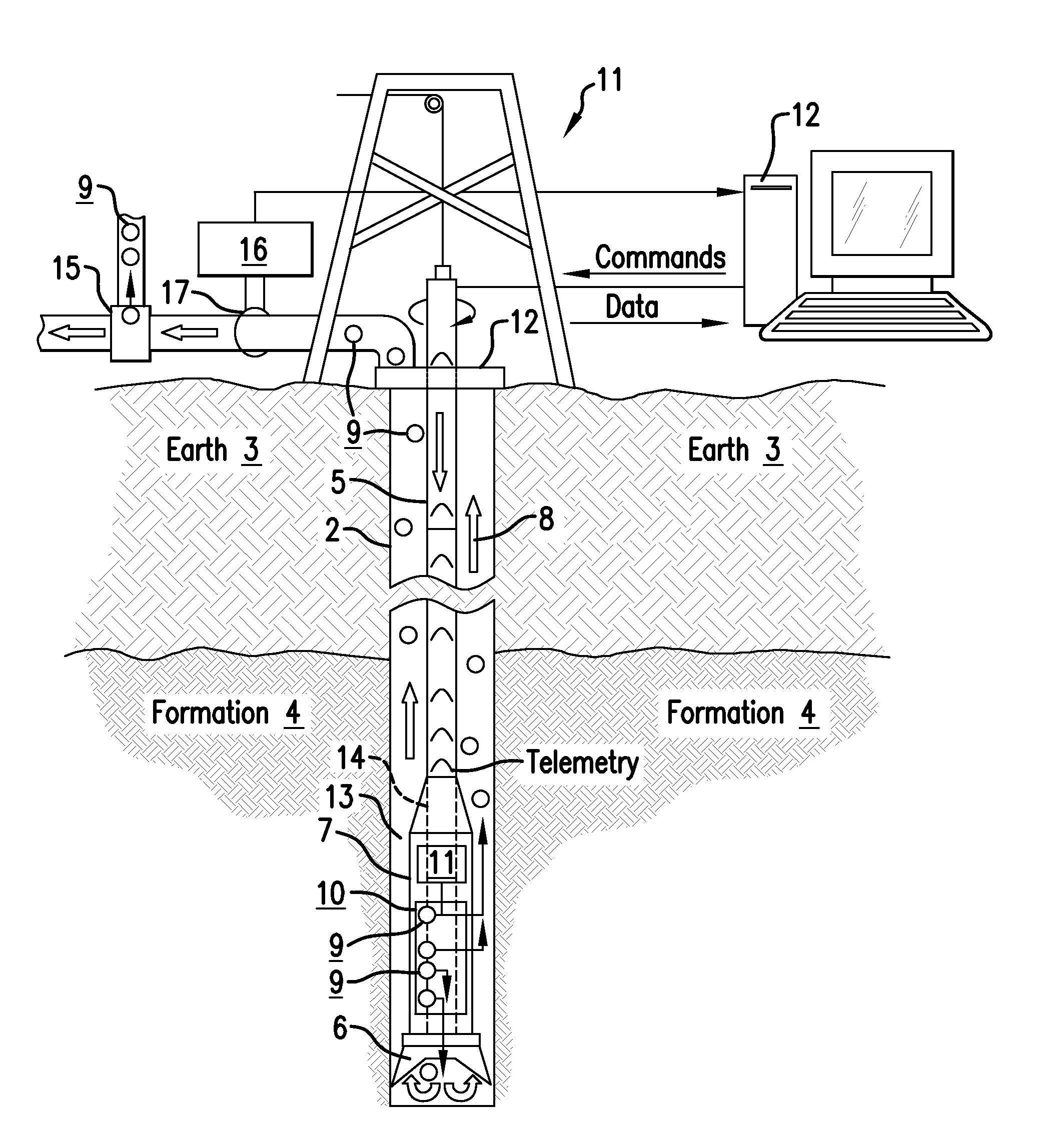
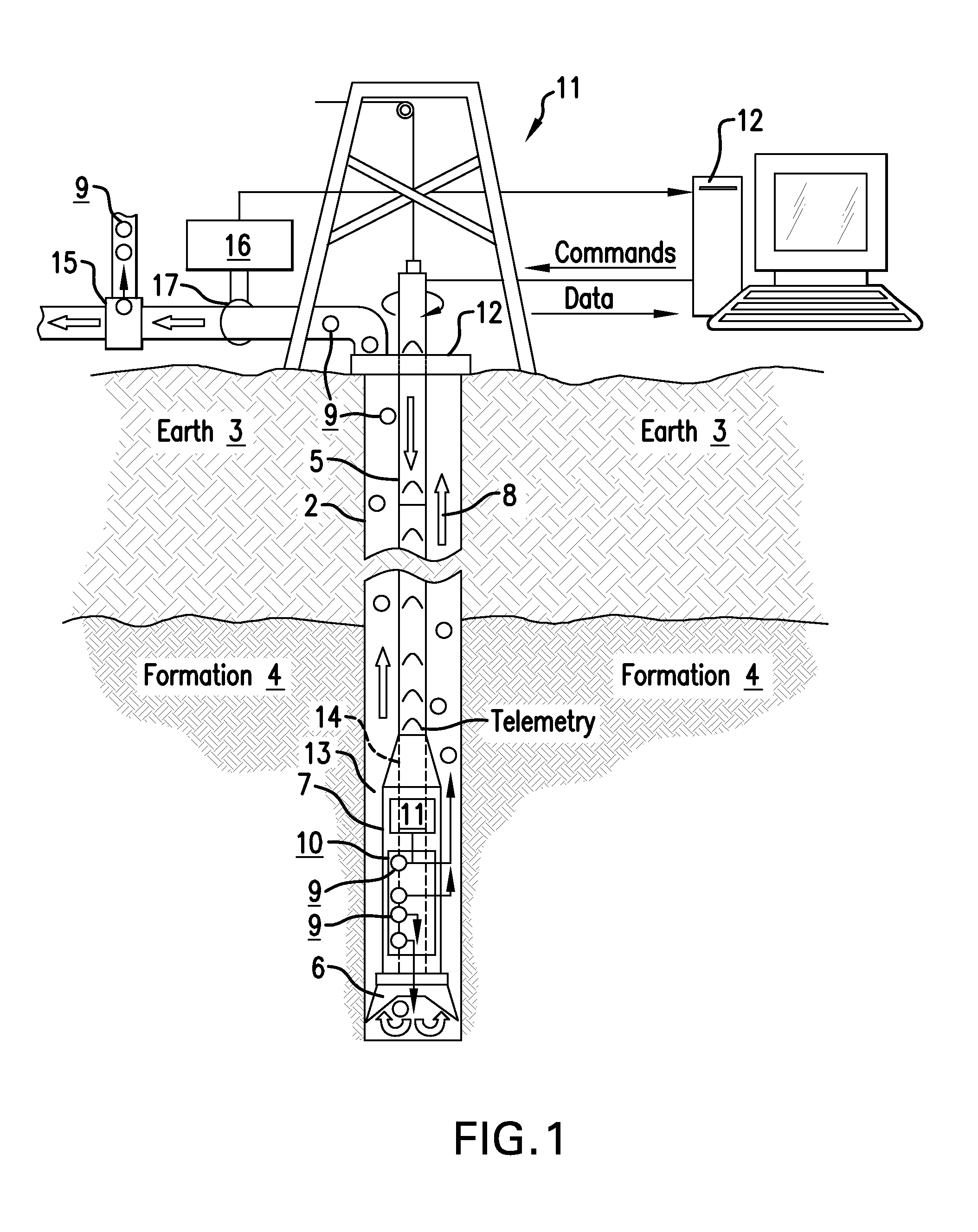
[0012]A detailed description of one or more embodiments of the disclosed apparatus and method presented herein by way of exemplification and not limitation with reference to the Figures.

[0013]FIG. 1 illustrates an exemplary embodiment of a drill string 5 disposed in a borehole 2 penetrating the earth 3, which includes a formation 4. The formation 4 represents any downhole material of interest. A drill string rotation system 12 disposed at a drill rig 11 at the surface of the earth 3 is configured to rotate the drill string 5 in order to rotate a drill bit 6 disposed at a distal end of the drill string 5. The drill bit 6 represents any cutting device configured to cut through the earth 3 or rock in the formation 4 in order to drill the borehole 2. Disposed adjacent to the drill bit 6 is a bottom hole assembly (BHA) 7. The drill bit 6 can be included in the BHA 7 or it can be separate from it. The BHA 7 can include downhole components such as a downhole tool 10 and a mud motor (not sh...


PUM


Abstract

Disclosed is an apparatus for estimating a downhole property of interest. The apparatus includes a carrier configured to be conveyed in a borehole penetrating an earth formation and carry a releasable sensor. The sensor is configured to be released by the carrier into drilling fluid and to sense the property. The sensor includes a memory to store sensed property data. The data can be downloaded from the memory wirelessly with the sensor in the drilling fluid or by retrieving the sensor from the drilling fluid.

Description

BACKGROUND[0001]In wellbore operations, the condition of a wellbore, a downhole tool, a reservoir, or fluid in the wellbore is typically measured by sensors in proximity to the drill bit and transmitted to the surface of the earth by a downhole telemetry system. Alternatively, the condition information is stored in memory disposed in a downhole tool and accessed by downloading the data upon retrieval of the tool from the wellbore. While a downhole telemetry system can transmit sensor data generally continuously, the overall transmission of data may be slow due to limited bandwidth. Similarly, while downloading data from a retrieved downhole tool may be performed with high bandwidth transmission, it can take from a few hours to days in order to retrieve the tool. Both methods may be ultimately too slow when downhole conditions are rapidly changing. Hence, it would be appreciated in the drilling industry if data obtained from downhole sensors could be provided to drilling operators in...

Claims


Application Information

Patent Timeline
IPC IPC(8): E21B47/00
CPCE21B47/124E21B41/0085E21B47/26
Inventor KUMAR, SUNIL
Owner BAKER HUGHES INC
Features
  • Generate Ideas
  • Intellectual Property
  • Life Sciences
  • Materials
  • Tech Scout
  • Unparalleled Data Quality
  • Higher Quality Content
  • 60% Fewer Hallucinations
Learn More