Apparatus, Process, and System for Monitoring the Integrity of Containers

a technology for integrity monitoring and containers, applied in the direction of material flaw investigation, instrumentation, reradiation, etc., can solve the problems of reducing the safety of operators, requiring frequent inspection, and reducing the proportion of the refractory surface in contact with the molten metal during processing

Active Publication Date: 2013-05-16
PROCESS METRIX
View PDF3 Cites 36 Cited by
  • Summary
  • Abstract
  • Description
  • Claims
  • Application Information

AI Technical Summary

Problems solved by technology

As known in the art, these containers are normally lined with refractory material installed, in brick form or cast in monolithic blocks in order to protect the metallic part of the vessel from the high-temperature contents placed therein; however, due to normal wear and tear of the refractory material through the combined effects of oxidation, corrosion and mechanical abrasion, some portion of the refractory surface in contact with the molten metal is lost during processing, thus requiring frequent inspection so as to assure extended use by performing early localized repair in order to avoid catastrophic failures and unnecessary or premature refurbishment of the entire vessel's refractory lining.
Such an approach introduces a combination of art and science, exposes the.container operator to unnecessary industrial hazards, reduces the frequency of inspections, and lacks the desired accuracy.
In addition, costs associated with the installation and repair of ceramic linings have increased significantly over the past twenty years as refractory materials have been reformulated for application-specific installations.
However, as summarized below, these conventional techniques have several limitations.
As to conventional techniques configured to measure quantitative refractory wear directly by use of a laser, for example, because the diameters of the lasers are of finite sizes (e.g., approximately 40 to 60 mm in some applications), potential refractory defects with characteristic dimensions smaller than the laser beam diameter, such as a small hole in the lining, are very difficult, if not impossible, to detect, making the localized piece of missing brick'also difficult to detect.
In addition, localized slag buildup on interior ladle surfaces may make it difficult to detect areas were lining repairs may be needed.
However, for any single heat, techniques that use lasers are not capable of resolving the difference between remaining refractory and slag build-up on the interior ladle surfaces.
As such, in the presence of slag accumulation, the system will over-predict the lining thickness or under predict the amount of lost refractory—both undesirable limitations in practice.
Finally, another potential problem that may not be detected by laser-based system is the result of fining, which occurs when molten steel naturally enters small gaps (e.g., small openings with a characteristic dimension of approximately 1-5 mm) that develop between the bricks in a refractory-lined vessel.
Minor finning only causes localized heating of the ladle shell.
However, with time, minor fining may become severe and result in melting of the ladle shell and subsequently leakage of molten steel.
Thus, while conventional contouring systems are a useful tool to characterize the interior profile of the vessel, there are situations in which the apparent'thickness measurement alone may not be sufficient to prevent breakouts.
This qualitative measurement gives an indication of hot spots on the ladle shell independent of the cause (i.e., impending failures due to thinning of the lining, or finning, or both) and, as such, are a direct measure of the nominal health of the “containment.” However, those of ordinary skill in the applicable arts will understand that these techniques only provide qualitative information and are not capable of providing detailed information characterizing the wear rate of the lining itself.
Thus, the external temperature measurements are only useful on a relative basis, and the lack of quantitative information in the data precludes determination of wear rates and refractory optimization in the ladle.

Method used


Image

  • Apparatus, Process, and System for Monitoring the Integrity of Containers
  • Apparatus, Process, and System for Monitoring the Integrity of Containers
  • Apparatus, Process, and System for Monitoring the Integrity of Containers

Examples


Embodiment Construction

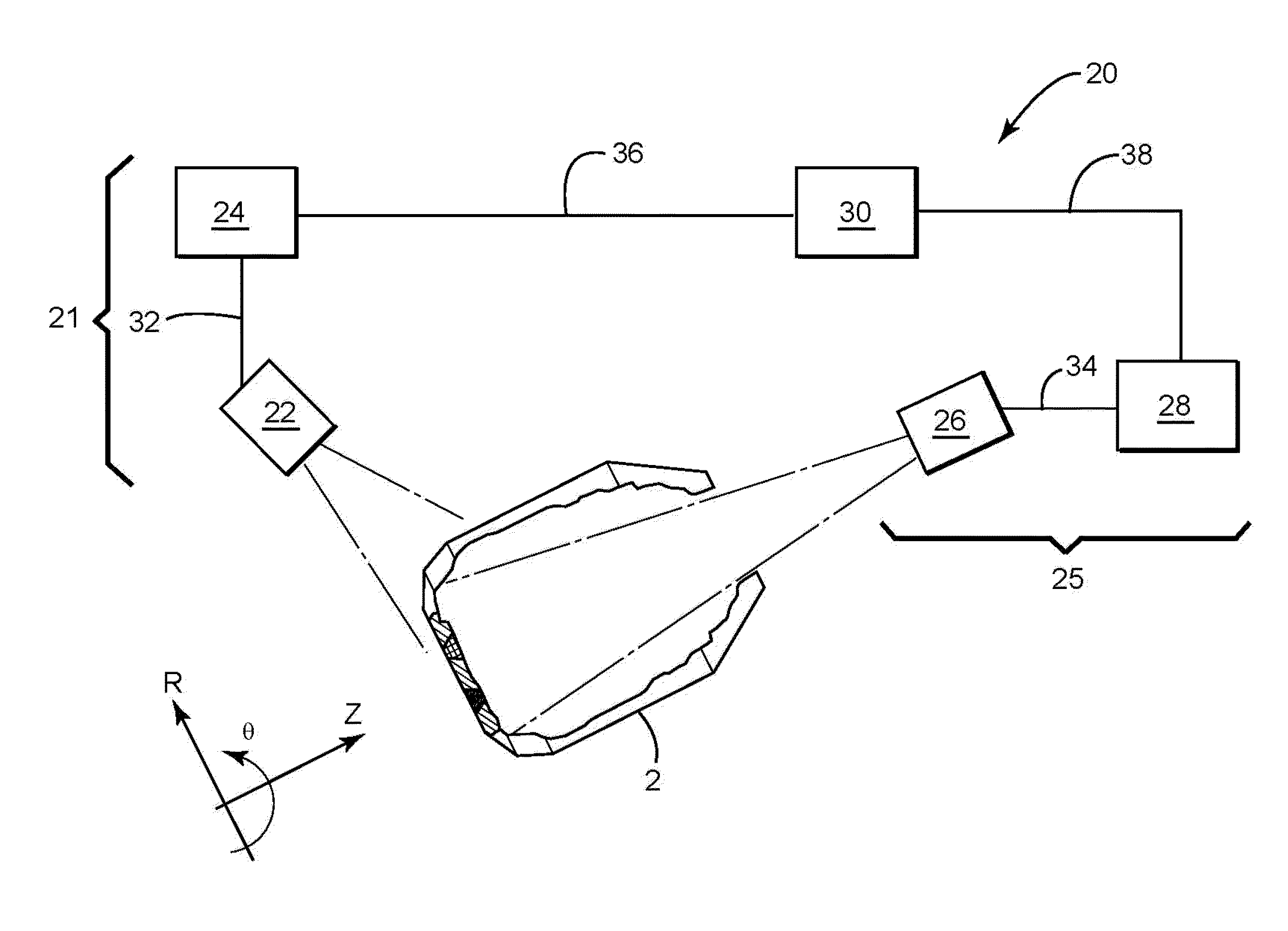
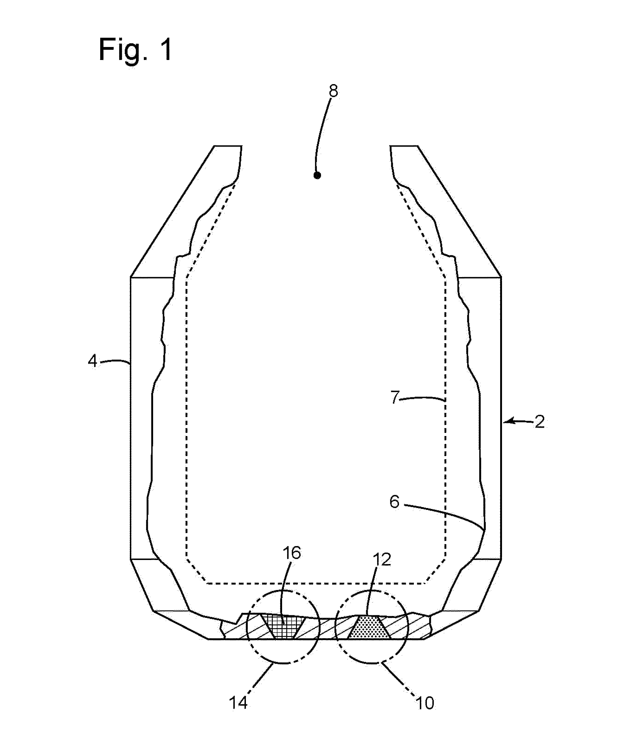
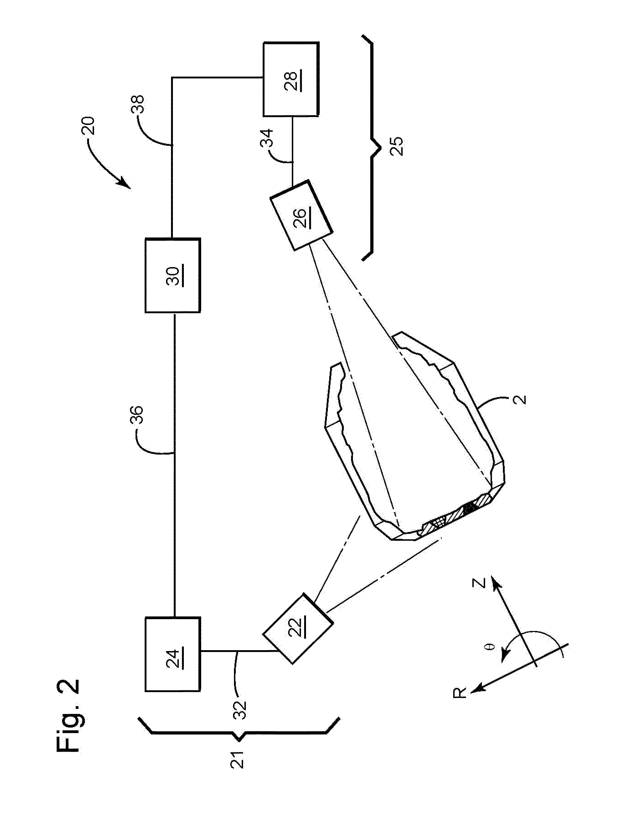
[0023]The following description of the exemplary embodiments refers to the accompanying drawings. The same reference numbers in different drawings identify the same or similar elements. The following detailed description does not limit the invention. Instead, the scope of the invention is defined by the appended claims. The following embodiments are discussed, for simplicity, with regard to the terminology and structure of apparatuses, systems, or methods capable of detecting potential failure locations in a container having a lining material to protect the same against elevated temperatures in a steel making application. However, the embodiments to be discussed next are not limited to these sets, but may be applied to other containers having a liner material exposed to an elevated temperature as compared to the melting point of the material of which the container is made, whose liner integrity needs to be determined in order to avoid unexpected failures.

[0024]Reference throughout t...


PUM

PropertyMeasurementUnit
sizesaaaaaaaaaa
thicknessesaaaaaaaaaa

Abstract

Apparatuses, systems, and methods to monitor the integrity of a container protected by a refractory material are disclosed having a first radiation detector to measure an external surface temperature of the container, a first radiation source to measure a thickness of the refractory material, and a central controller configured to display to a user the measurement of the external surface temperature of the container and the measurement of the thickness of the refractory material.

Description

BACKGROUND[0001]1. TECHNICAL FIELD[0002]Embodiments of the subject matter disclosed herein relate generally to apparatuses, methods and systems and, more particularly, to mechanisms and techniques for monitoring vessels or containers configured to hold materials having an elevated temperature.[0003]2. DISCUSSION OF THE BACKGROUND[0004]Metallic vessels or containers of various sizes and shapes designed to hold materials at elevated temperatures are widely used in many industrial applications. Example of these applications include, but are not limited to, gasification processes in chemical and power production, Electric-Arc Furnaces (EAF), Basic Oxygen Furnaces (BOF), ladles, blast furnaces, degassers, and Argon-Oxygen-Decarburization (AOD) furnaces in steel manufacturing. As known in the art, these containers are normally lined with refractory material installed, in brick form or cast in monolithic blocks in order to protect the metallic part of the vessel from the high-temperature c...

Claims


Application Information

Patent Timeline
Patent Type & Authority Applications(United States)
IPC IPC(8): G01N21/00G01S17/86
CPCG01N25/72F27D2021/0085G01S17/88G01S17/023G01B11/06G01S17/86
Inventor BONIN, MICHEL PIERREHARVILL, THOMAS LAWRENCEHOOG, JARED HUBERT
Owner PROCESS METRIX
Why Eureka
Try Eureka