Method to make a curved tubular element in order to convey abrasive materials such as concrete or suchlike, and curved tubular element thus obtained

Active Publication Date: 2013-05-23
CIFA
View PDF8 Cites 15 Cited by
  • Summary
  • Abstract
  • Description
  • Claims
  • Application Information

AI Technical Summary

Benefits of technology

The patent is about a reinforcement insert in a tubular body. The reinforcement insert is placed in a way that it is symmetrical when looking at a plane that passes through both the outer and inner sides of the tubular body. This design helps to make the finished product stronger and more uniform.

Problems solved by technology

In particular, near the extrados of the curved tubular element the speed at which the concrete is conveyed is much higher than the speed near the intrados, that is, in the zone with the smallest radius of curvature, and therefore the inner surface of the curved tubular element near the extrados is subject to greater wear.
The known curved tubular element has the disadvantage, however, that it is rather complex to make, is very heavy and very expensive.
Moreover, given the curved conformation of the tubular element, it is difficult to introduce the second tubular part inside the first tubular part due to the need to force both parts.
However, this known solution does not eliminate all the disadvantages and makes it difficult to produce the element; a further clamping step of the second tubular part with respect to the first is also necessary.

Method used


Image

  • Method to make a curved tubular element in order to convey abrasive materials such as concrete or suchlike, and curved tubular element thus obtained
  • Method to make a curved tubular element in order to convey abrasive materials such as concrete or suchlike, and curved tubular element thus obtained
  • Method to make a curved tubular element in order to convey abrasive materials such as concrete or suchlike, and curved tubular element thus obtained

Examples


Embodiment Construction

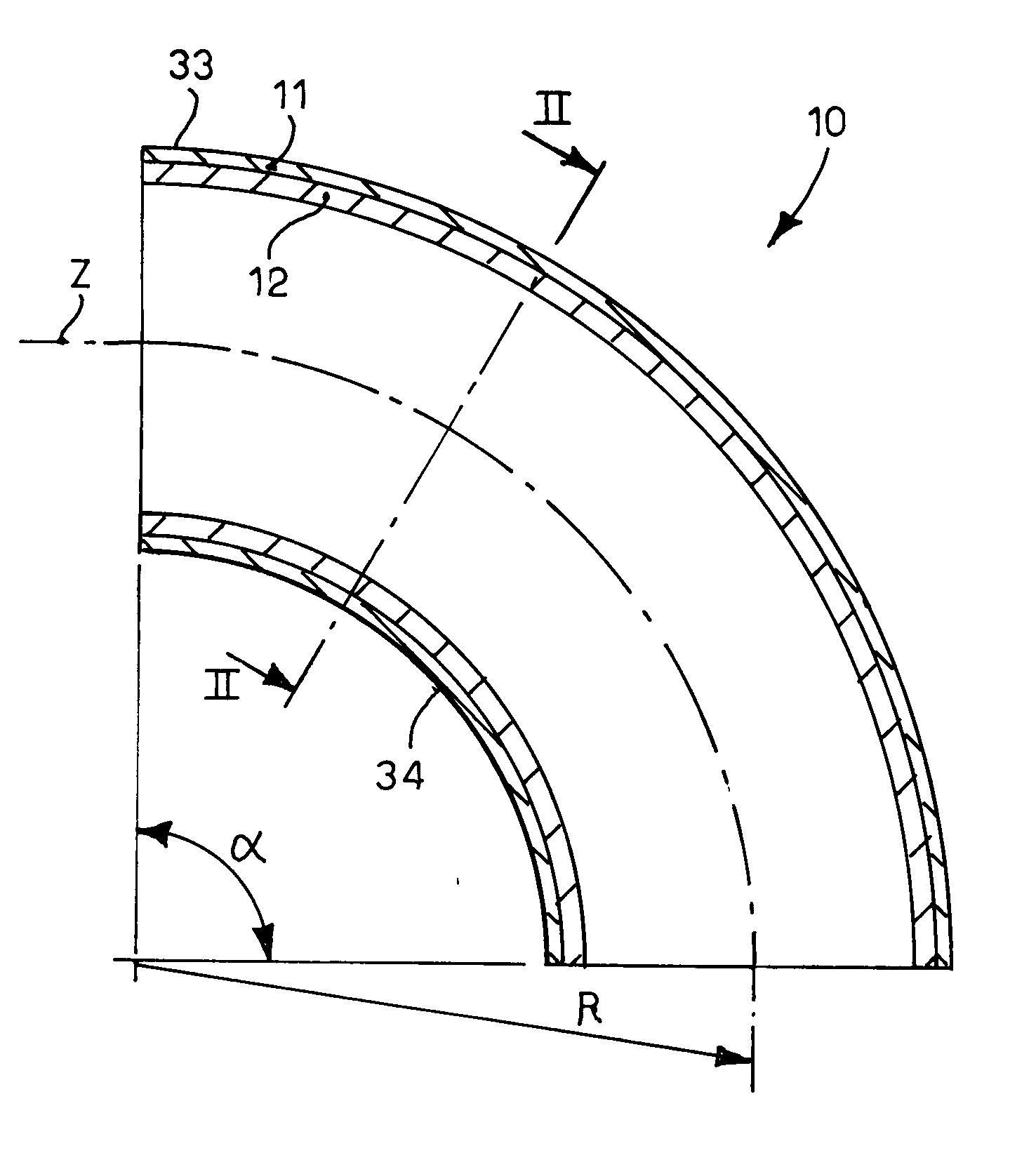
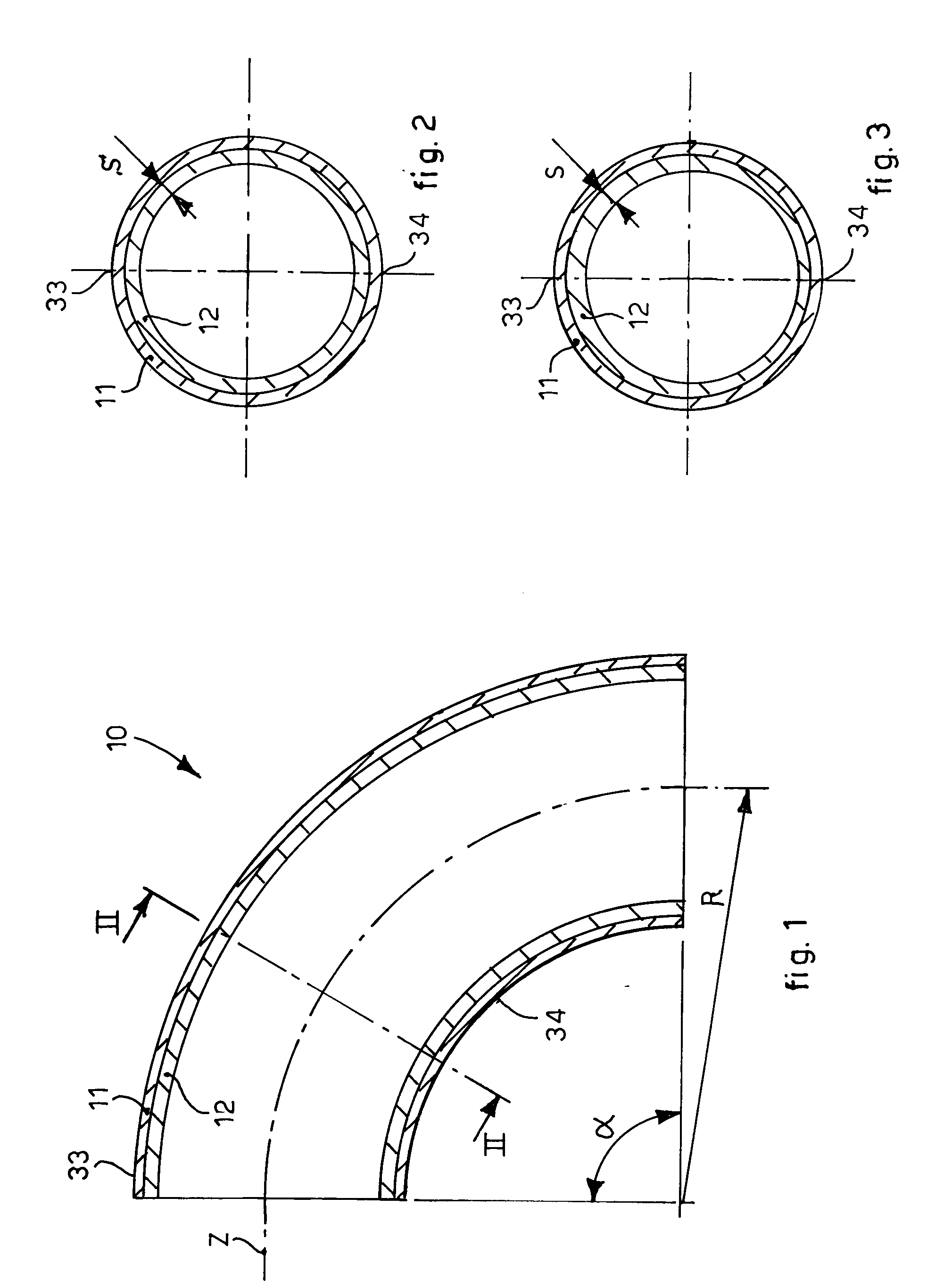
[0037]With reference to FIG. 1, a curved tubular element 10, for conveying abrasive materials such as concrete or suchlike, according to the present invention comprises a tubular body 11, or outer body, and an inner curved reinforcement component, in this case a second body 12 which is directly present inside the tubular body 11.

[0038]The outer tubular body 11 is preferably made of metal material such as carbon steel or light alloys based on aluminum or other materials.

[0039]To give a non-restrictive example, the outer tubular body 11 is made of aluminum and has an inner diameter of about 125 mm, its thickness is about 7 mm, and it has a mean radius of curvature R of about 240 mm.

[0040]The second inner body 12 is made of wear-resistant material such as for example ceramic materials, high resistance steels, cast iron, chrome carbides or other types of carbides, and has a higher melting temperature than the material of which the tubular body 11 is made.

[0041]The outer tubular body 11 ...


PUM

PropertyMeasurementUnit
Angleaaaaaaaaaa
Angleaaaaaaaaaa
Angleaaaaaaaaaa

Abstract

Method to make a curved tubular element in order to convey abrasive materials such as concrete or suchlike, which comprises a first step of making at least a curved component made of a material highly resistant to wear, having an arched transverse development comprised between 90° and 360°, a second step of inserting said curved component into a shaping mold with a molding surface with a shape mating with the outer surface of at least a part of the curved tubular element to be made, so that, together with said molding surface, said curved component defines a casting chamber, and a third step in which material with a low resistance to wear is cast in said casting chamber in order to make, externally to said curved component, at least a part of a tubular body of said curved tubular element.

Description

FIELD OF THE INVENTION[0001]The present invention concerns a method to make a curved tubular element, suitable to be connected with other rectilinear or curved elements, and to define a pipe to convey concrete or other abrasive material in the fluid state. In particular, the field of application of the present invention is the building trade, however it may also be used in other industrial fields.BACKGROUND OF THE INVENTION[0002]In the construction field, it is known to use metal tubular elements of a modular type that are suitably connected to each other to form a pipe that allows to transfer concrete from a container, for example a concrete mixer, to the casting zone, by means of pumping devices.[0003]The tubular elements are connected to each other on each occasion depending on the characteristics of the zone to be reached. In particular, to allow a possible change in direction, the rectilinear tubular elements are connected to curved tubular elements which have standardized angl...

Claims


Application Information

Patent Timeline
IPC IPC(8): F16L9/02
CPCF16L43/00F16L9/02F16L57/06B22D19/045B22D19/02F16L43/001B22D11/006
Inventor CIPOLLA, DAVIDEFERRE, FABIO
Owner CIFA
Why Eureka
Try Eureka