Stirring apparatus

Inactive Publication Date: 2013-05-23
SAMSUNG TECHWIN CO LTD
View PDF0 Cites 18 Cited by
  • Summary
  • Abstract
  • Description
  • Claims
  • Application Information

AI Technical Summary

Benefits of technology

[0013]One or more exemplary embodiments

Problems solved by technology

However, after the above process is performed, impurities as well as a target material may adhere to the beads.
In this case, the impurities which adhered onto the surfaces of the beads located outside the lump may be easily removed while the impurities adhered onto the surfaces of the beads located inside the lump may not be

Method used


Image

  • Stirring apparatus
  • Stirring apparatus
  • Stirring apparatus

Examples


Embodiment Construction

[0039]Hereinafter, exemplary embodiments will be described in detail with reference to the attached drawings.

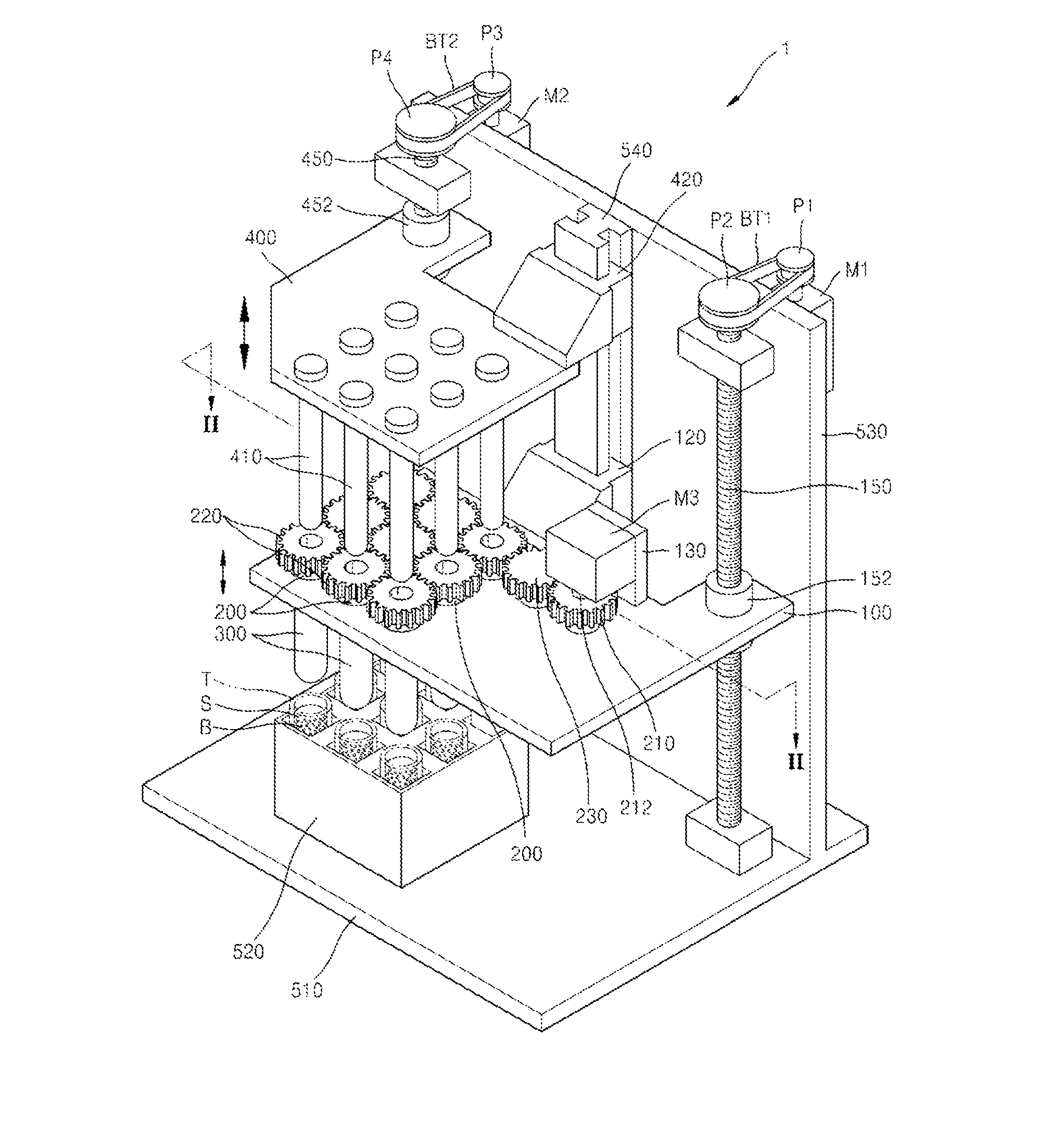
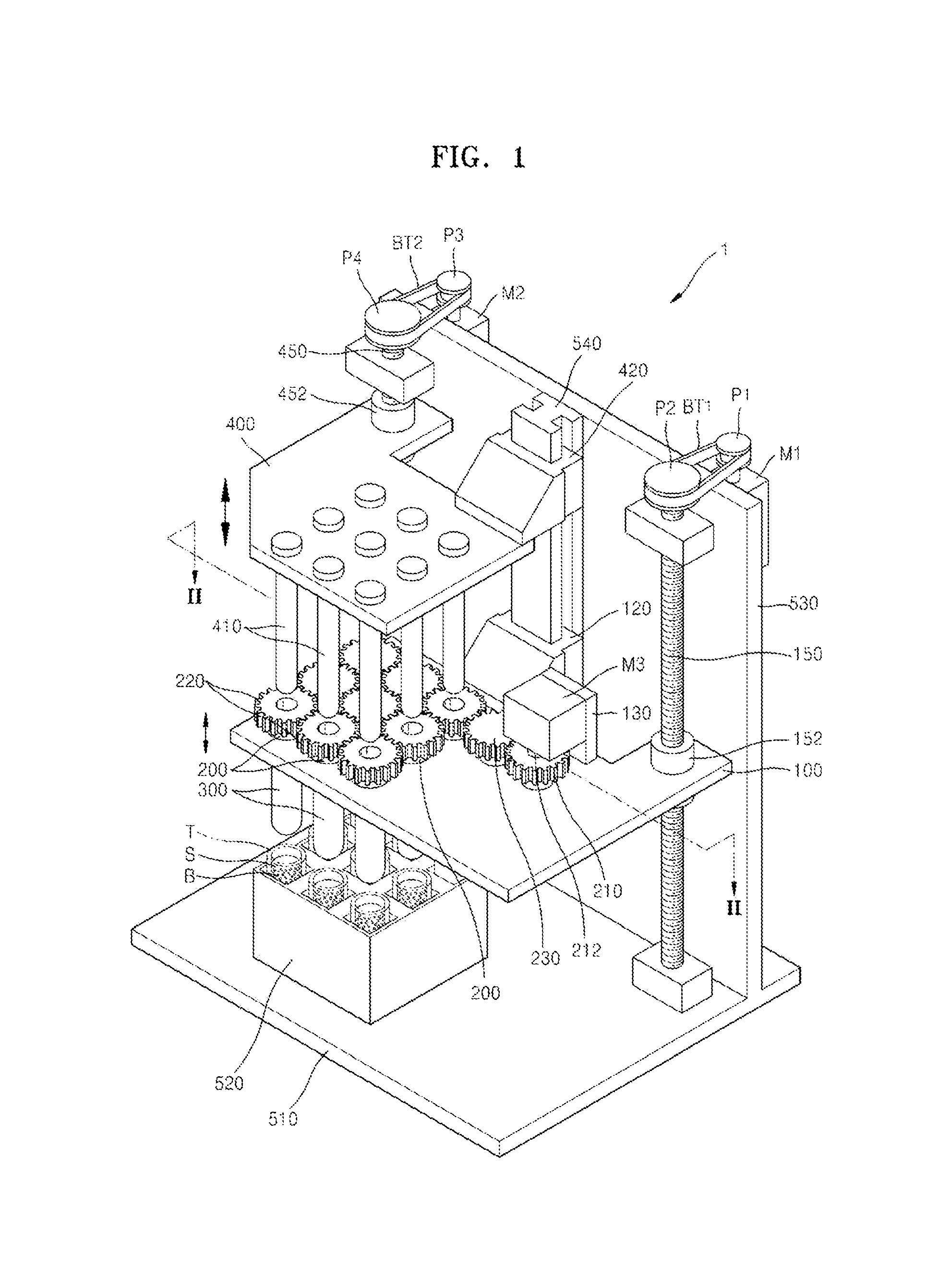
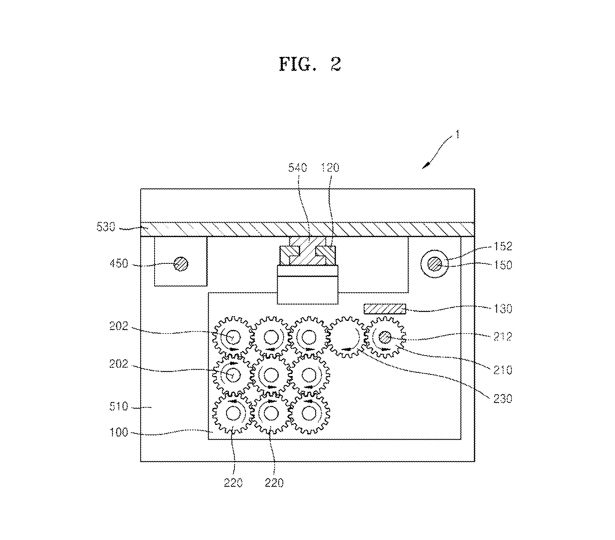
[0040]FIG. 1 is a perspective view of a stirring apparatus 1 according to an exemplary embodiment. FIG. 2 is a cross-sectional view cut along a line II-II of the stirring apparatus 1 illustrated in FIG. 1. FIG. 3 is a cross-sectional view of an example of a portion of the stirring apparatus 1 illustrated in FIG. 1. FIGS. 4 through 6 are front views showing operation of the stirring apparatus 1 illustrated in FIG. 1.

[0041]The stirring apparatus 1 according to the current exemplary embodiment is used to stir materials included in a sample S. The stirring apparatus 1 may also be used to capture magnetic beads B included in the sample S, in which case, the stirring apparatus 1 may be referred to as a magnetic beads separator. Furthermore, since the stirring apparatus 1 may be used in an overall process for capturing or extracting a biological material, for example, in lysis, stir...


PUM

PropertyMeasurementUnit
Timeaaaaaaaaaa
Poweraaaaaaaaaa
Tensionaaaaaaaaaa

Abstract

A stirring apparatus and a method of separating magnetic beads from a sample including the magnetic beads are provided. The stirring apparatus includes at least one rotational body having a hollow formed therein; a driving unit which moves upward and downward and rotates the at least one rotational body; a cap which is combined with the rotational body, extends in a vertical direction, and has an internal space connected to the hollow of the rotational body; and a magnetic force application unit which moves upward and downward to be inserted into or taken out of the internal space of the cap via the hollow of the rotational body.

Description

CROSS-REFERENCE TO RELATED PATENT APPLICATION[0001]This application claims priority from Korean Patent Application No. 10-2011-0121192, filed on Nov. 18, 2011 in the Korean Intellectual Property Office, the disclosure of which is incorporated herein in its entirety by reference.BACKGROUND[0002]1. Field[0003]Apparatuses and methods consistent with exemplary embodiments relate to stirring and mixing a liquid with another liquid, a solid, or powder, or separating magnetic beads from a sample including the magnetic beads.[0004]2. Description of the Related Art[0005]Currently, research is active in the biotechnology industry. In particular, research is actively conducted on technologies of extracting, transforming, and utilizing biological materials such as nucleic acid. The above research inevitably requires a method or apparatus for selectively extracting a certain target to be observed.[0006]In the target extracting method or apparatus, technologies of increasing the efficiency of ext...

Claims


Application Information

Patent Timeline
IPC IPC(8): B03C1/30B01F13/08
CPCB03C1/30B01F7/005B01F7/161B01F9/002B01F9/0021B01F9/0023G01N35/0098B01F15/00454B01F15/00681B03C1/032B03C1/286B03C2201/26B01F11/0022B01F27/116B01F27/806B01F29/33B01F29/321B01F29/322B01F31/24B01F35/3231B01F35/4111B03C1/02B01F27/80B01F33/45B01F35/00
Inventor OK, JI-TAEKIM, SEONG-KOOK
Owner SAMSUNG TECHWIN CO LTD
Why Eureka
Try Eureka