
Turn signal lighting system for a motor vehicle, and method of operating a turn signal lighting system

Inactive Publication Date: 2013-05-23
AUDI AG
View PDF12 Cites 40 Cited by
  • Summary
  • Abstract
  • Description
  • Claims
  • Application Information

AI Technical Summary

Benefits of technology

The present invention provides a method for producing a turn signal lighting system for motor vehicles that meets legal requirements for an illumination zone while creating an impression of a gradually expanding illumination area using sequential activation of LED groups. Each LED group has multiple light emitting diodes, making the circuitry simpler to produce. The technical effect is a visually appealing and progressive illumination during a turn signal, which is perceived by an observer as a flowing motion.

Problems solved by technology

It is, however, impossible for technical reasons to have all signal lamps illuminate at precisely the same time.
This means that a moving pattern of light in the illuminated area from one side to another during flashing is not permitted.

Method used


Image

  • Turn signal lighting system for a motor vehicle, and method of operating a turn signal lighting system
  • Turn signal lighting system for a motor vehicle, and method of operating a turn signal lighting system
  • Turn signal lighting system for a motor vehicle, and method of operating a turn signal lighting system

Examples


Embodiment Construction

[0025]Throughout all the figures, same or corresponding elements may generally be indicated by same reference numerals. These depicted embodiments are to be understood as illustrative of the invention and not as limiting in any way. It should also be understood that the figures are not necessarily to scale and that the embodiments are sometimes illustrated by graphic symbols, phantom lines, diagrammatic representations and fragmentary views. In certain instances, details which are not necessary for an understanding of the present invention or which render other details difficult to perceive may have been omitted.

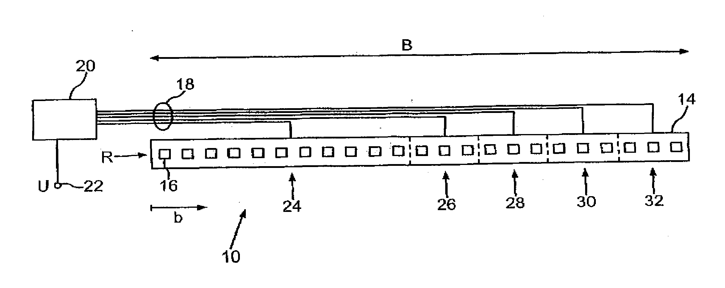
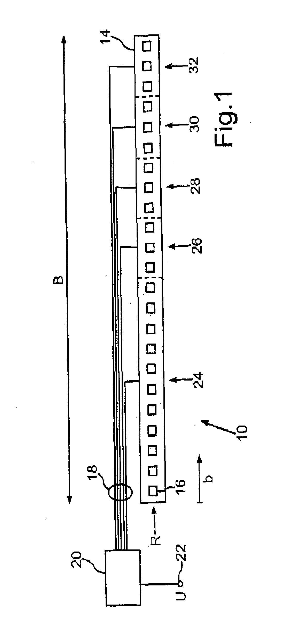
[0026]Turning now to the drawing, and in particular to FIG. 1, there is shown a schematic illustration of one embodiment of a turn signal lighting system according to the present invention, generally designated by reference numeral 10. FIG. 1 shows the inside of the turn signal lighting system 10 which is installed in a taillight of a passenger car. The turn signal lighting ...


PUM


Abstract

In a method of operating a turn signal lighting system, in a flashing cycle a first group of a plurality of LED groups arranged in a row is initially activated, with each of the LED groups including at least one light emitting diode. Thereafter, the other groups of the plurality of LED groups are successively activated until the plurality of LED groups are all in an ON state. The plurality of LED groups is then maintained in the ON state for a predetermined time period before being deactivated. The overall time period from activating the first group of the plurality of LED groups up until reaching the ON state of the plurality of LED groups ranges hereby from 100 ms to 200 ms.

Description

CROSS-REFERENCES TO RELATED APPLICATIONS [0001]This application claims the priority of German Patent Application, Serial No. 10 2011 119 230.5, filed Nov. 23, 2011, pursuant to 35 U.S.C. 119(a)-(d), the content of which is incorporated herein by reference in its entirety as if fully set forth herein.BACKGROUND OF THE INVENTION [0002]The present invention relates to a turn signal lighting system for a motor vehicle, and method of operating a turn signal lighting system.[0003]The following discussion of related art is provided to assist the reader in understanding the advantages of the invention, and is not to be construed as an admission that this related art is prior art to this invention.[0004]Turn signal lighting systems, or short signal lamps, are used in motor vehicles to indicate a travel direction and are alternatingly turned on or off within a flashing cycle, i.e. each flashing cycle includes an active period during which the signal lamp illuminates and an inactive period dur...

Claims


Application Information

Patent Timeline
IPC IPC(8): B60Q1/34
CPCB60Q1/38B60Q1/34B60Q2900/40B60Q1/381
Inventor STADLER, MANFREDSCHWARZ, TORSTENLENDLE, REINERHUMMEL, BENJAMIN
Owner AUDI AG
Features
  • Generate Ideas
  • Intellectual Property
  • Life Sciences
  • Materials
  • Tech Scout
  • Unparalleled Data Quality
  • Higher Quality Content
  • 60% Fewer Hallucinations
Learn More