
Goose Decoy with Head and Tail Movement

a head and tail movement technology, applied in the field of goose decoys, to achieve the effect of quick and easy snapping

Active Publication Date: 2019-06-20
WISYS TECH FOUND
View PDF0 Cites 3 Cited by
  • Summary
  • Abstract
  • Description
  • Claims
  • Application Information

AI Technical Summary

Benefits of technology

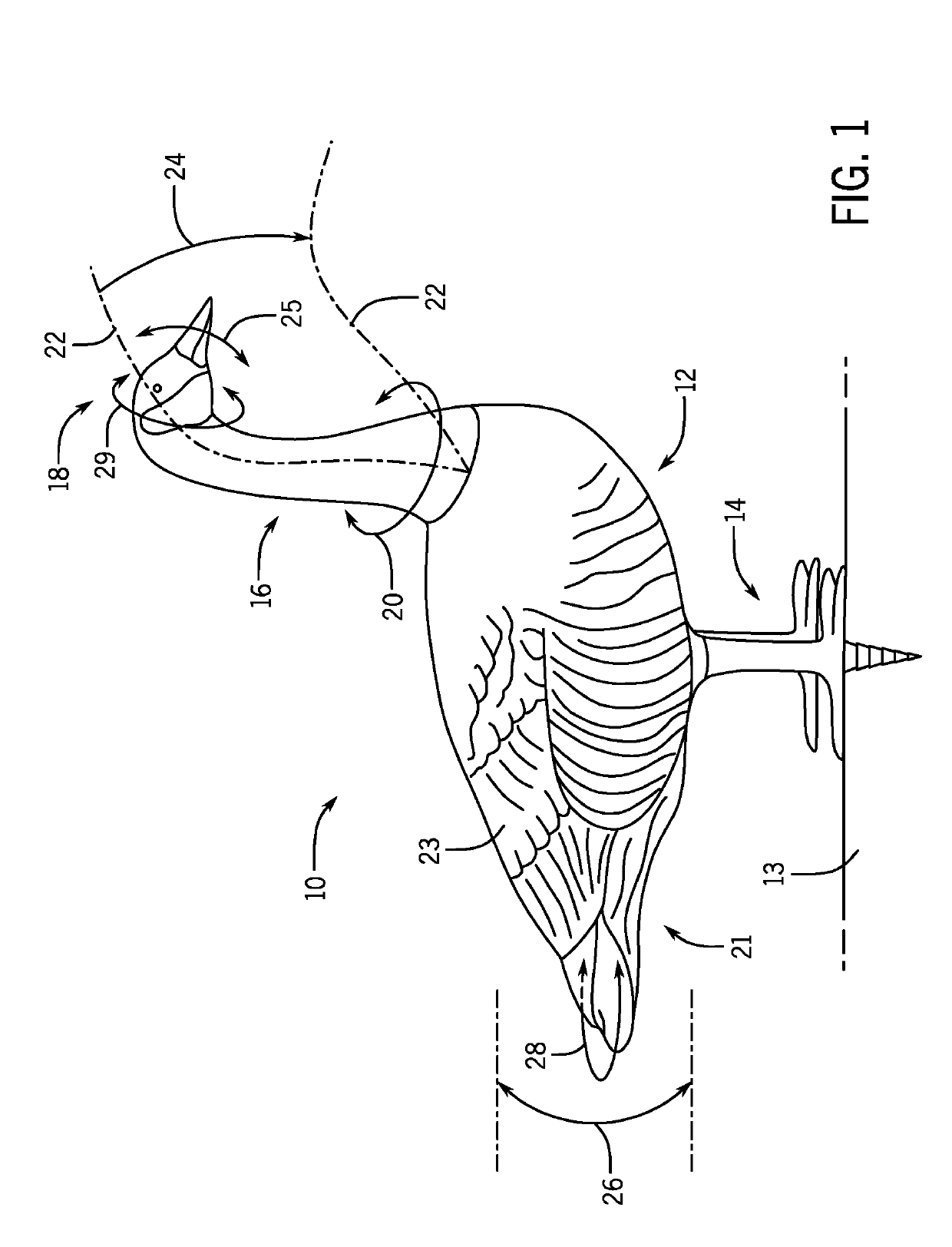
The patent describes a game bird decoy with a flexible neck that can move in both horizontal and vertical directions. The neck is made up of inter-engaging neck segments that pivot to curve forward along a neck axis. A tension band is attached to each segment and follows any curvature of the neck axis. The neck also has tabs and pins that fit into corresponding bore holes on opposite sides, allowing for simple interconnection of the neck segments. The tension band can be adjusted to control the movement of the decoy's neck. The technical effects of the invention include improved flexibility, realistic movement, and better protection against environmental contaminants.

Problems solved by technology

While the motion may enhance the life-like quality of the decoys, poorly implemented movement can scare away wildfowl and provide the opposite desired effect.

Method used


Image

  • Goose Decoy with Head and Tail Movement
  • Goose Decoy with Head and Tail Movement
  • Goose Decoy with Head and Tail Movement

Examples


first embodiment

Neck Section—First Embodiment

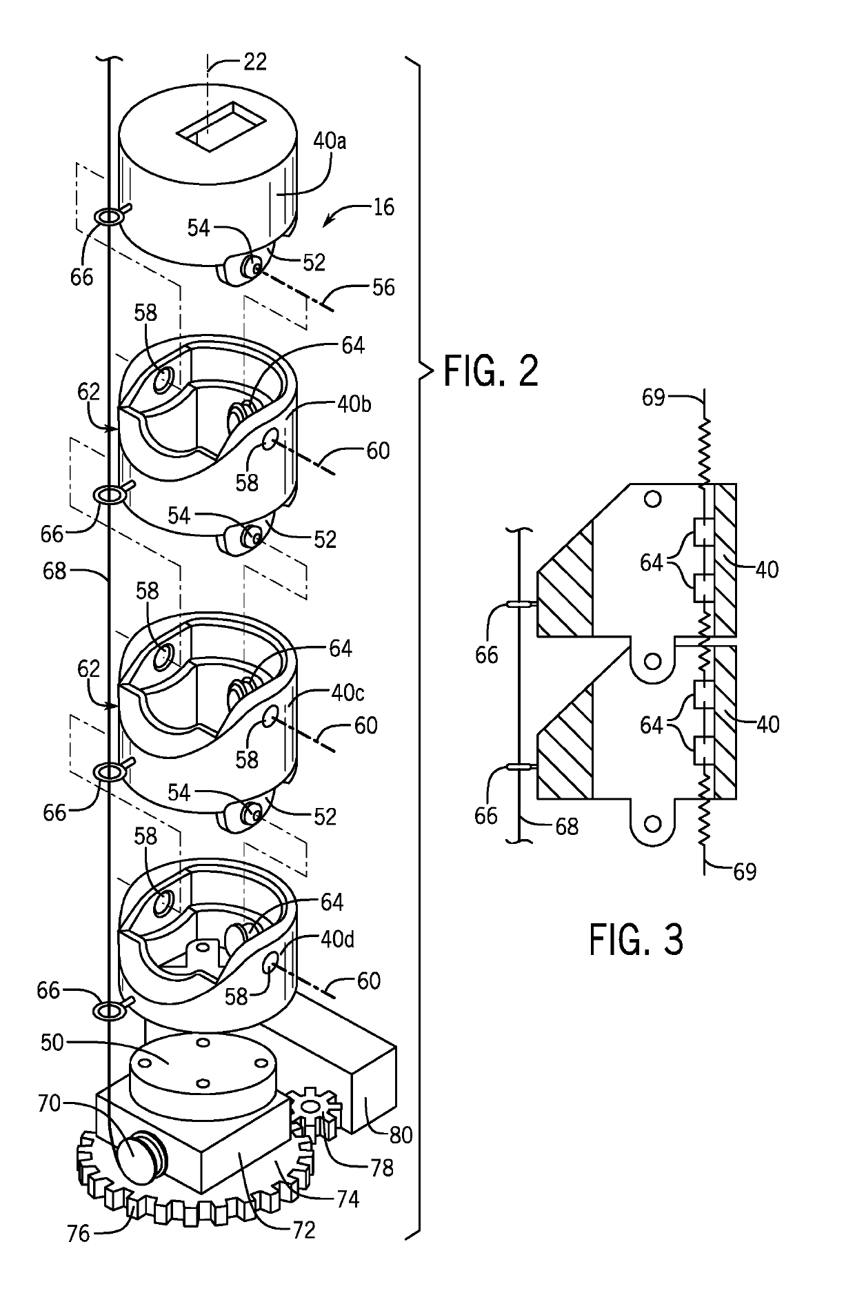
[0060]Referring to FIG. 2, the vertebrae segments 40 of the neck section 16 may be injection molded from a thermoplastic polymer for simplicity and manufacture. In this regard various styles of vertebrae segments 40 may be constructed including a top vertebrae segment 40a that may be attached to the head swivel joint 36 (shown in FIG. 6) or directly to a head element 18, five to seven intermediate vertebrae segments 40 (40b and 40c as shown), and a base vertebrae segment 40d that may attach to a swivel or rotating platform 50 as will be discussed below.

[0061]Referring also to FIG. 3, each of the vertebrae segments 40 except for the base vertebrae segment 40d may have two downwardly extending interconnection tabs 52 on opposite sides of the lower end of the vertebrae segment 40 having outwardly extending pins 54 coaxial along a horizontal axis 56 and generally perpendicular to the neck axis 22. These pins 54 fit within corresponding bore holes 58 also pos...

second embodiment

Neck Section—Second Embodiment

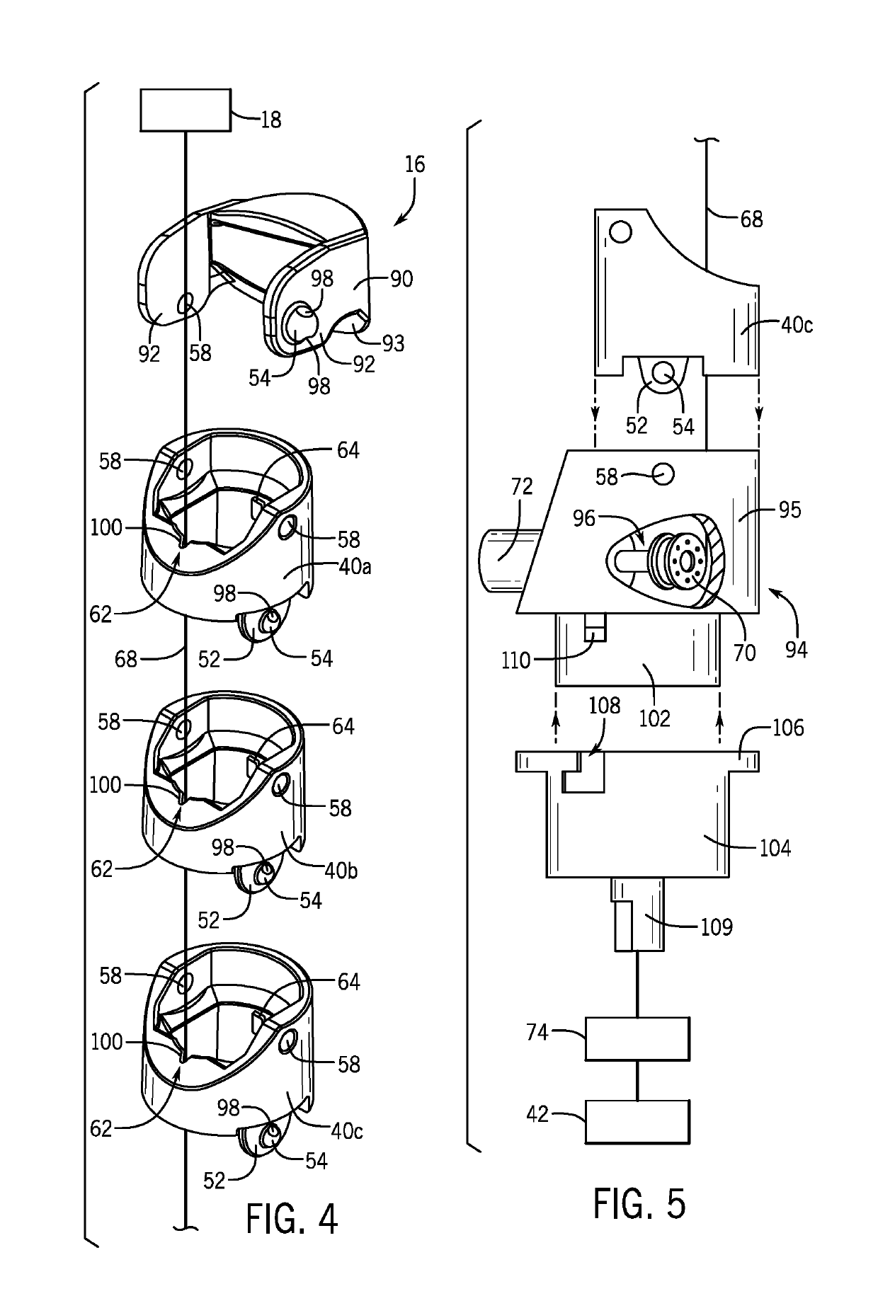
[0065]Referring to FIGS. 4 and 5, in an alternative embodiment, the vertebrae segments 40 of the neck section 16 may be as substantially shown in FIGS. 2 and 3 with various modifications applied to the vertebrae segments 40 as further explained below.

[0066]Similar to above, the vertebrae segments 40 may be injection molded from a thermoplastic polymer for simplicity and manufacture. In this regard, a select number of vertebrae segments 40, for example, 7 to 9 vertebrae segments (40a, 40b, 40c are shown) may span between a head connector 90 connected to be a head segment 18 and a base connector 94 connecting the bottommost vertebrae segment 40c to a motor assembly 96 therein.

[0067]Each of the intermediate vertebrae segments 40a, 40b, 40c, may include two downwardly extending interconnection tabs 52 on opposite sides of the lower end of the vertebrae segment 40 with outwardly extending pins 54. Pins 54 fit within corresponding bore holes 58 by a snap fit ...


PUM


Abstract

A moving decoy that better captures the natural movements of a goose or similar game bird in critical aspects, most notably, the characteristic, highly flexible goose neck and the wagging of the tail is provided. The invention provides an improved set of neck vertebrae for use in this application and may operate as integrated into the rest of the decoy or as a modular neck modular neck may be attached to a variety of different decoys. Actuation of the neck may be provided by self-contained electrical motor and power unit in the latter case. In an alternative embodiment remote access of the neck may be provided by cables run between the decoy and a remote location.

Description

CROSS REFERENCE TO RELATED APPLICATION[0001]This application claims the benefit of U.S. Provisional Application No. 40 / 607,384, filed Dec. 19, 2017 and U.S. Provisional Application No. 40 / 618,251, filed Jan. 17, 2018, both of which are hereby incorporated by reference.STATEMENT REGARDING FEDERALLY SPONSORED RESEARCH OR DEVELOPMENT[0002]--BACKGROUND OF THE INVENTION[0003]The present invention relates to goose decoys, and in particular, to a goose decoy with natural neck and tail movement.[0004]Hunting decoys are devices used for hunting wildfowl. For example, the hunting decoys are placed about the hunting area to encourage wild birds to land nearby and within the range of a nearby concealed hunter.[0005]Types of decoys for wildfowl may include simple silhouette decoys that are two-dimensional representations of geese or three-dimensional life-size models of geese that are meant to simulate the presence of geese. The three-dimensional models are preferred over the two-dimensional mod...

Claims


Application Information

Patent Timeline
Patent Type & Authority Applications(United States)
IPC IPC(8): A01M31/06G08C17/02
CPCA01M31/06G08C17/02G08C2201/10
Inventor FICK, JOHNALVAREZ, JOSEHANSON, SAMSCHNERING, SCOTTSTOFFEL, JOSEPHWELSH, ROBERTDUBAN, KEVINGOETSCH, KARLHUNGER, ADAMOLSON, CONNORPECKHAM, WILL
Owner WISYS TECH FOUND
Learn More