

General banding and codec banding artifact removal
a general banding and codec technology, applied in image data processing, color television, television systems, etc., can solve the problems of not explicitly identifying and protecting the texture region, the effect of not being able to handle “new false contours” is small, and the effect of affecting the quality of the image is not obvious
- Summary
- Abstract
- Description
- Claims
- Application Information
AI Technical Summary
Benefits of technology
Problems solved by technology
Method used
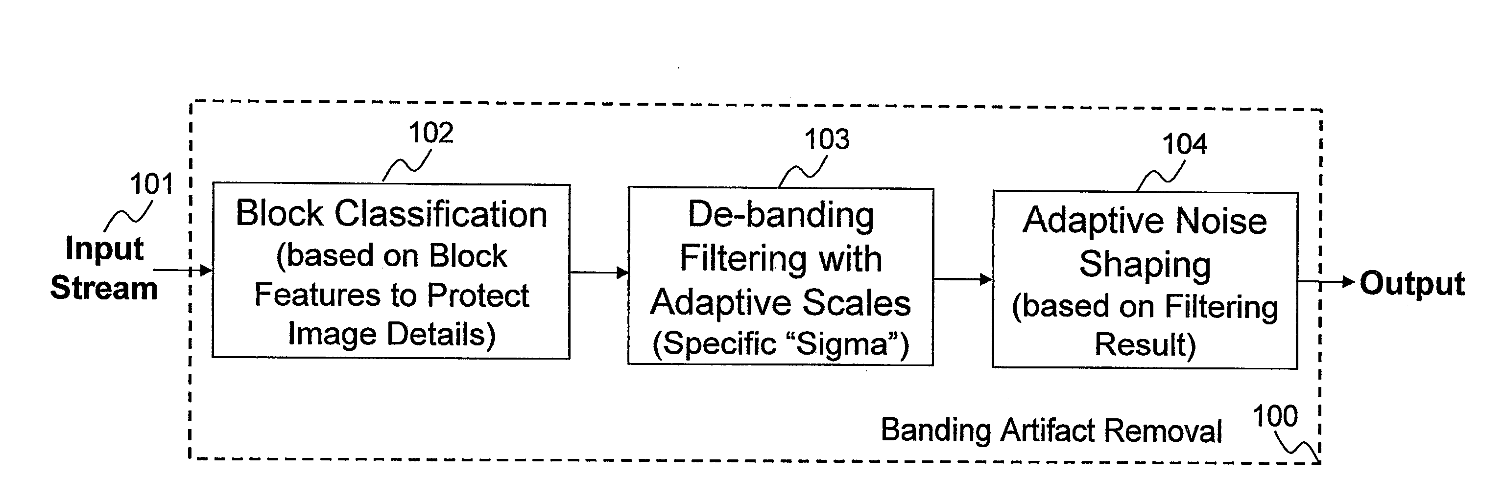
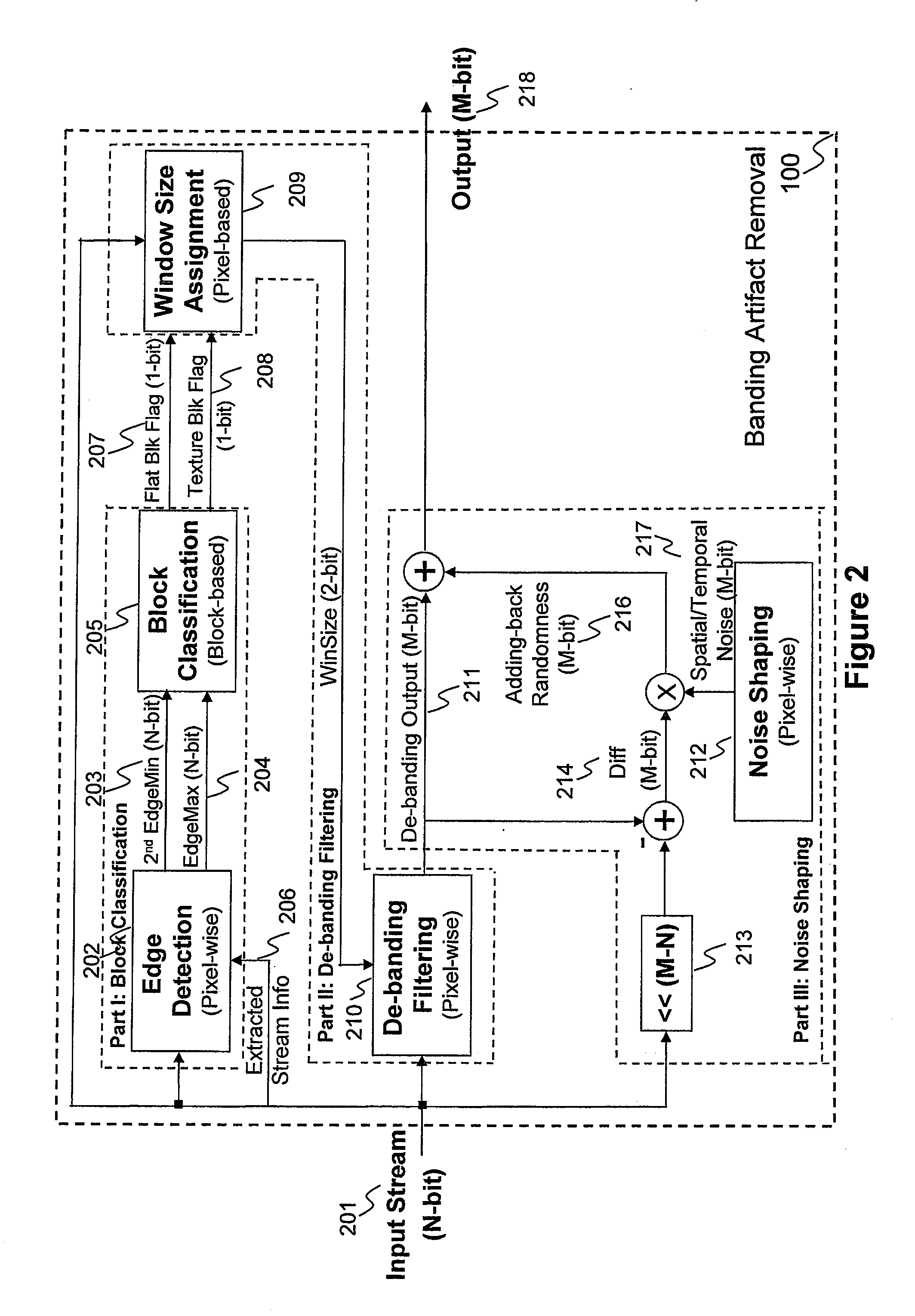
Image

Examples
Embodiment Construction
[0018]Embodiments of the present invention are hereafter described in detail with reference to the accompanying figures. Although the invention has been described and illustrated with a certain degree of particularity, it is understood that the present disclosure has been made only by way of example and that numerous changes in the combination and arrangement of parts can be resorted to by those skilled in the art without departing from the spirit and scope of the invention.
[0019]The following description with reference to the accompanying figures is provided to assist in a comprehensive understanding of exemplary embodiments of the present invention as defined by the claims and their equivalents. It includes various specific details to assist in that understanding, but these are to be regarded as merely exemplary. Accordingly, those of ordinary skill in the art will recognize that various changes and modifications of the embodiments described herein can be made without departing fr...
PUM
 Abstract
Description
Claims
Application Information