System for fastening bridge and temples in the manufacture of eyeglasses

a technology of fastening system and eyeglasses, which is applied in the direction of spectacles/goggles, instruments, spectacles/goggles, etc., can solve the problems of low mechanical strength, affecting the working time and conditions, eyeglasses cost, and relatively insecure fastening, etc., to achieve stable and secure manner, simple and quick, and easy assembly

Active Publication Date: 2013-05-23
LUXOTTICA SRL
View PDF5 Cites 29 Cited by
  • Summary
  • Abstract
  • Description
  • Claims
  • Application Information

AI Technical Summary

Benefits of technology

[0024]Another aim of the invention is to provide eyeglasses of the “ultralight” type whose lateral hinge elements can be associated with flat temples (also made, for example, by die forming from the same sheet or from another sheet of suitab

Problems solved by technology

All the prior art solutions of “ultralight” eyeglasses have had to overcome, for eyeglass solidity and durability, at least two structural problems connected with the firmness of the join between the edge of the lens and the central bridge element and with lens rattling relative to its fastening points.
Use of that solution, however, has revealed a first drawback in the fact that the pins made of plastic material, besides having low mechanical strength—for example, low shock resistance—must nevertheless be made and specifically fixed to, or incorporated in, the ends of the bridges and of the lateral hinge elements, since they are made of different materials at different times and in different moulds from the parts they must be joined to, thus influencing the working times and conditions, as well as the costs of the eyeglasses.
Another drawback of that solution is due to the fact that, in the case of lenses which are thicker than average, the uniform and limited height of the fastening pins provides a relatively insecure fastening because the relative penetration of the pins into the lenses makes the free ends of the securing sleeves excessively flexible.
A yet further drawback of the stated prior art system is due to the impossibility of applying the fastening pins to the bridges and hinge elements made, for example, by die forming or punching out of metal sheets not only because of the relatively reduced thickness of their structure but also because of the impossibility of solidly joining them to t

Method used


Image

  • System for fastening bridge and temples in the manufacture of eyeglasses
  • System for fastening bridge and temples in the manufacture of eyeglasses
  • System for fastening bridge and temples in the manufacture of eyeglasses

Examples


Embodiment Construction

[0075]In all the accompanying drawings, the same parts are denoted or intended to be denoted by the same reference numbers.

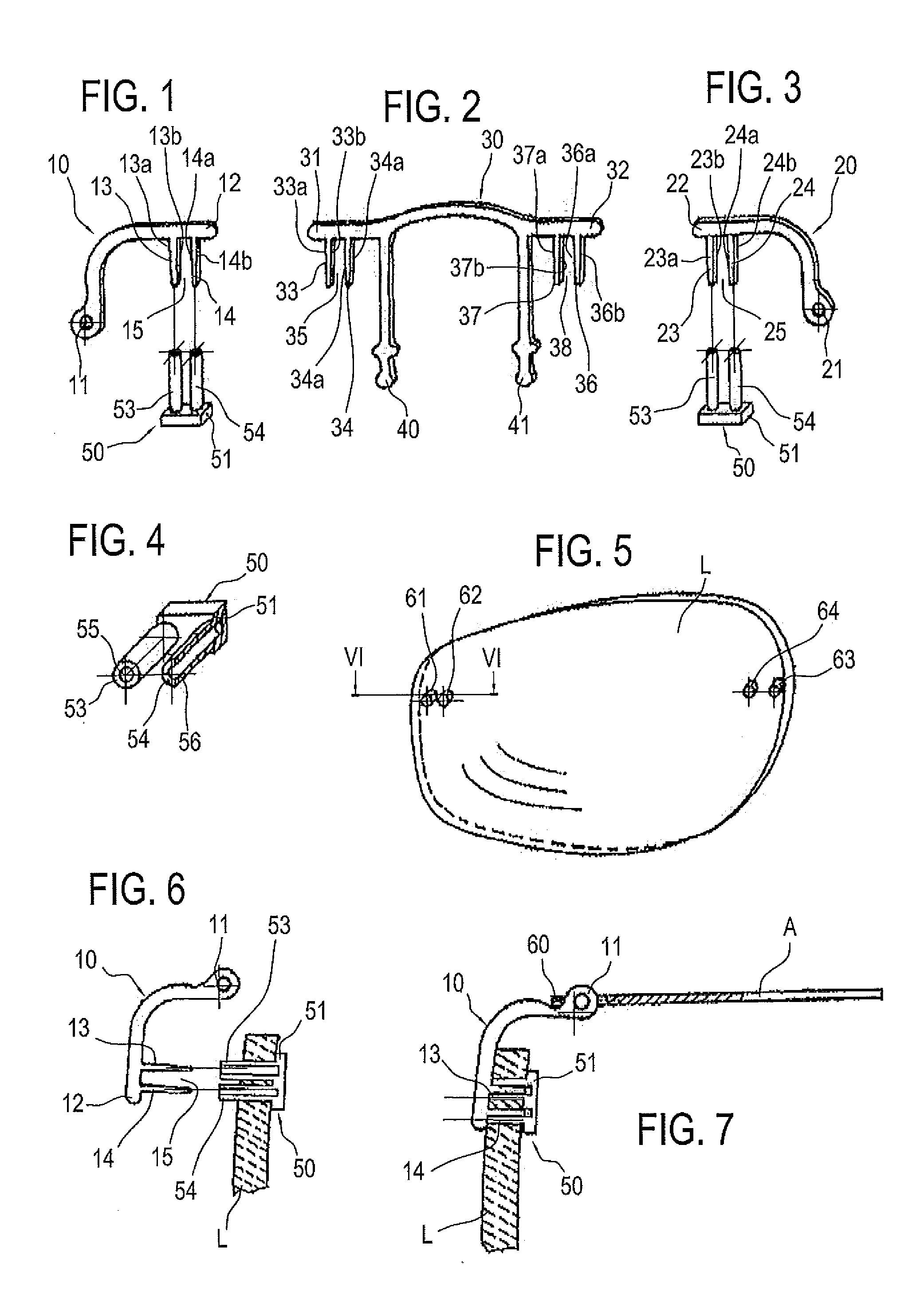
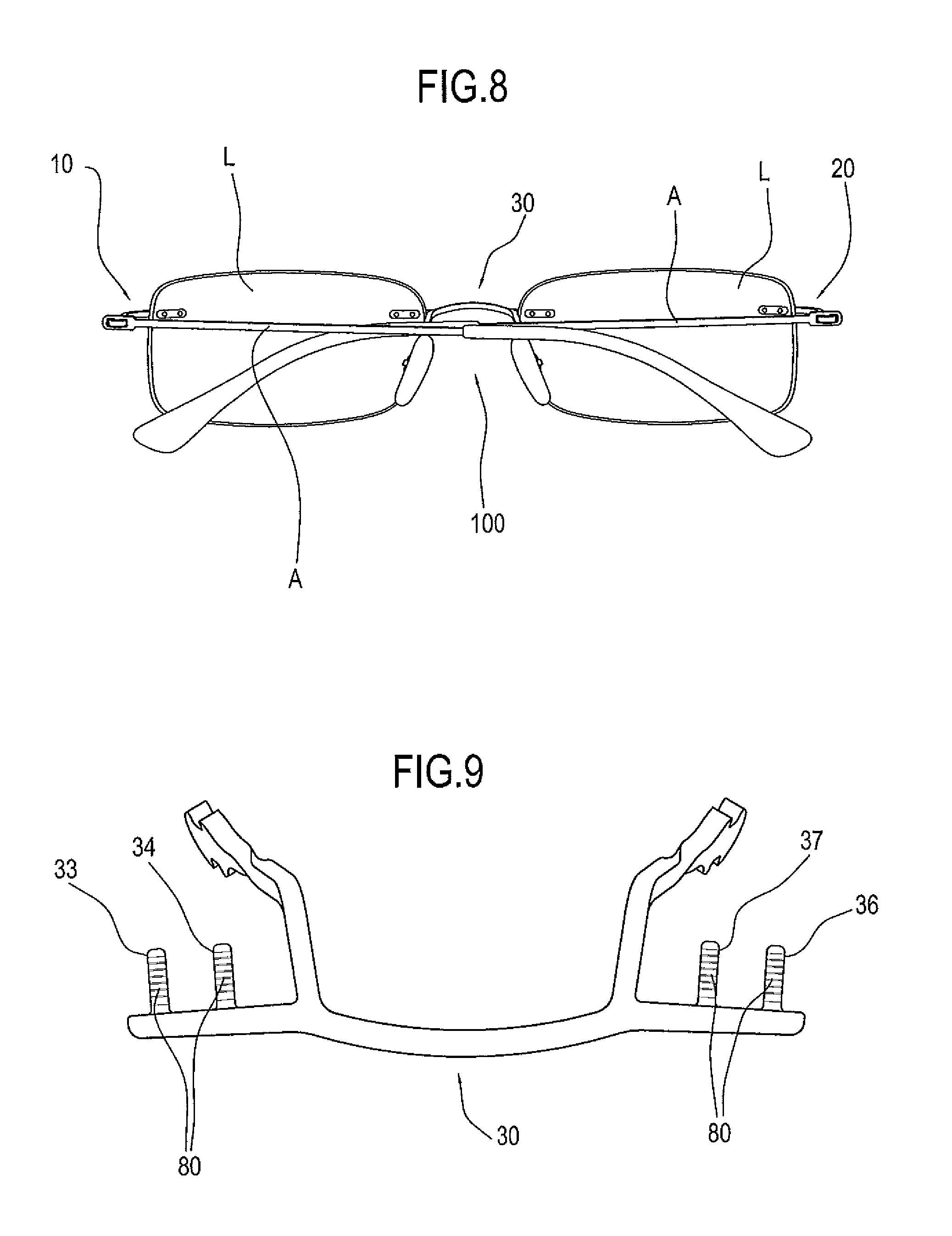
[0076]According to the solution of the invention as illustrated in the drawings, a pair of mutually opposed fronts or end pieces 10 and 20 and a central bridge 30 for mounting eyeglass lenses L can be formed from a single flat sheet of a suitable metal alloy, for example by die forming or punching, the sheet being uniform in thickness and constant in the quality of the material.

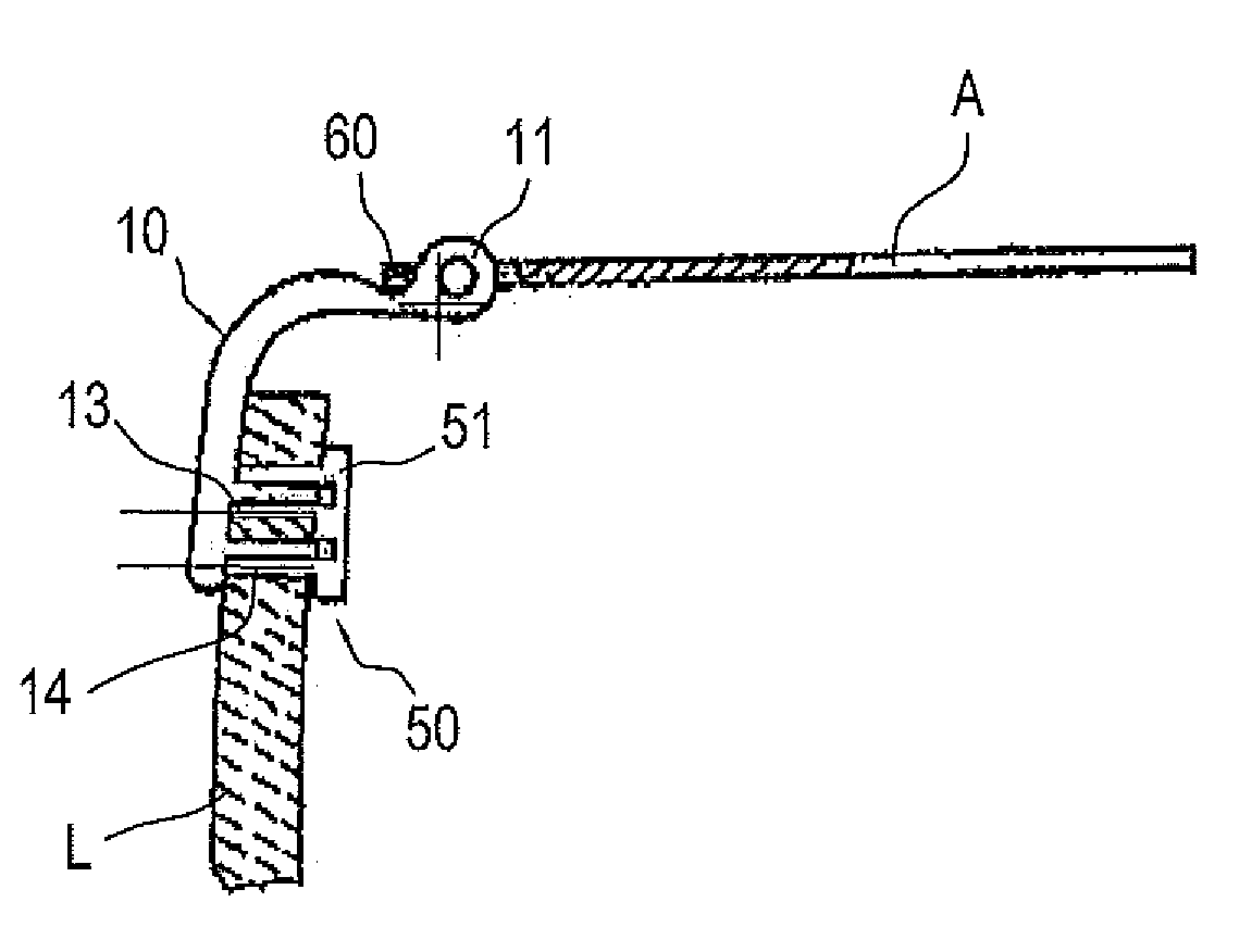
[0077]The end piece or hinge element 10 has an end with an eye 11, to be associated with the hinge end 60 of the temple A, while its opposite end 12, directed towards the lens, is in the shape of a fork, consisting of a pair of internal teeth or prongs 13-14, with a space or centre distance 15 between them.

[0078]Similarly, the end piece or hinge element 20 has an end with an eye 21, to be associated with the hinge end 60 of the opposite eyeglass temple A, while its opposite end 22, direct...


PUM

PropertyMeasurementUnit
Angleaaaaaaaaaa
Thicknessaaaaaaaaaa
Shapeaaaaaaaaaa

Abstract

The invention relates to a system for fastening the bridge (30) or the hinge elements (10, 20) connecting the temples (A) to the lenses (L) of eyeglasses, where the ends of the bridge (30), as well as each of the ends (12, 22) of the temple connecting hinge elements (10, 20) which is directed towards the respective lens is furnished with a respective fork-shaped structure, with at least one pair of prongs (33-34, 36-37, 13-14, 23-24) lying in the plane at right angles to the plane of the lenses and where each lens is provided with holes (61-62, 63-64) located at the points of connection with the ends of the bridge (30) and/or of the temple connecting hinge elements (10, 20). The holes are equal in number to the number of prongs on the respective fork-shaped structures and comprise, inside them, respective tubular sleeves (53, 54). The prongs of each fork-shaped structure are pressed into the tubular sleeves, are flat, and have lateral walls (13a-13b, 14a-14b, 23a-23b, 24a-24b, 33a-33b, 34a-34b, 36a-36b, 37a-38a) which are flat and smooth and other walls which are knurled.

Description

TECHNICAL FIELD[0001]This invention relates to a new system for fastening the central bridge and joining the lateral, temple hinge elements to the lenses of eyeglasses, especially but not necessarily of the type known as “ultralight” eyeglasses (also called “rimless” eyeglasses), that is to say, those without a full mounting frame structure, where the lenses are provided with front fastening and where the bridge and the lateral elements are made by die forming or punching out from a sheet of suitable metal alloy.BACKGROUND ART[0002]The traditional eyeglass frame consisting of a front rim, or central element, for fastening and supporting the lenses and whose ends are furnished with hinge elements for fastening and moving the temples, has been substantially revolutionized by the introduction of eyeglasses known as “ultralight” or “three-piece” eyeglasses where the lenses are joined directly to each other and to the temples solely by an interposed central bridge and a pair of lateral f...

Claims


Application Information

Patent Timeline
IPC IPC(8): G02C1/02G02C5/00G02C13/00
CPCG02C1/02G02C5/008Y10T29/31G02C5/00G02C13/001G02C2200/12G02C1/023
Inventor VIGNATO, ARCADIO
Owner LUXOTTICA SRL
Why Eureka
Try Eureka