

Microphone unit
a technology of microphones and units, applied in the direction of electrostatic transducers, electric transducers, microphones, etc., can solve problems such as operation defects
- Summary
- Abstract
- Description
- Claims
- Application Information
AI Technical Summary
Benefits of technology
Problems solved by technology
Method used
Image

Examples
first embodiment
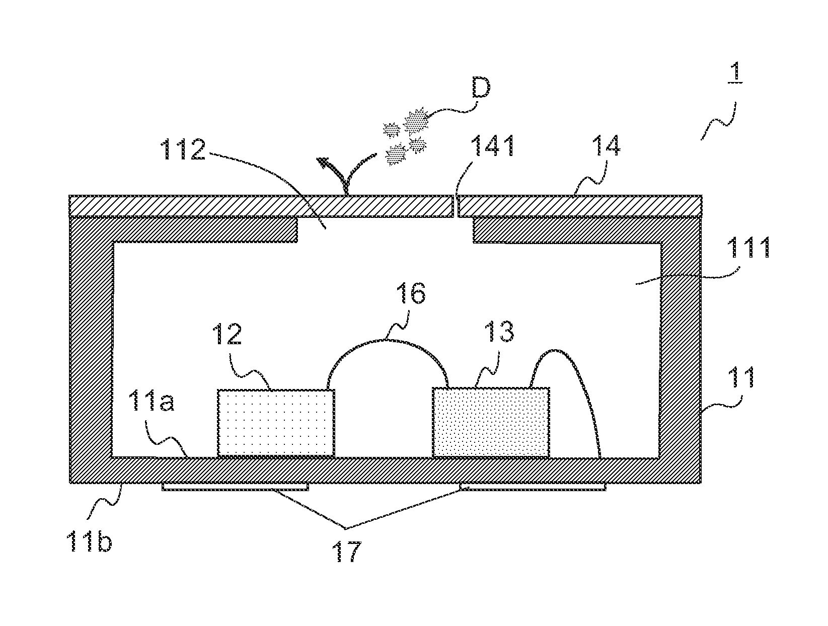
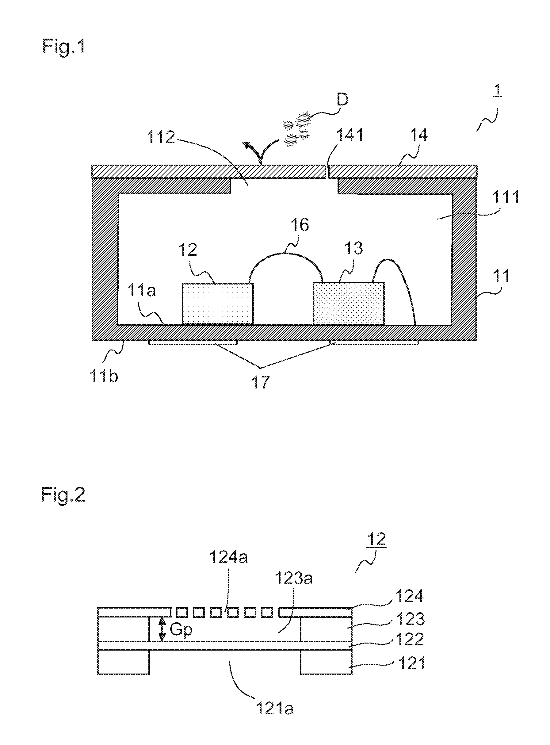
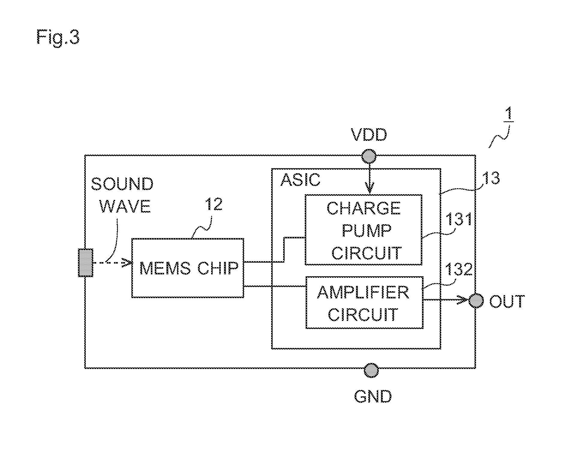
[0045]First, a microphone unit according to a first embodiment is described with reference to FIG. 1, FIG. 2, FIG. 3, FIG. 4A and FIG. 4B. FIG. 1 is a schematic sectional view showing a structure of the microphone unit according to the first embodiment to which the present invention is applied. FIG. 2 is a schematic sectional view showing a structure of a MEMS (Micro Electro Mechanical System) chip of the microphone unit according to the first embodiment. FIG. 3 is a block diagram showing a structure of the microphone unit according to the first embodiment. FIG. 4A and FIG. 4B are schematic views expecting a case where the microphone unit according to the first embodiment is viewed from a side (upper side) on which a film is disposed, that is, views showing a relationship among an internal pressure adjustment hole, an opening portion of a housing, and an adhesive portion (first adhesive portion). FIG. 4A is a view in a case where the adhesive portion is a first form, and FIG. 4B is ...
second embodiment
[0070]Next, a microphone unit according to a second embodiment is described with reference to FIG. 5A and FIG. 5B. FIG. 5A and FIG. 5B are schematic sectional views showing a structure of the microphone unit according to the second embodiment to which the present invention is applied. FIG. 5A shows a state of a case where the internal pressure is equal to the outside, and FIG. 5B shows a state of a case where the internal pressure rises.
[0071]The microphone unit 2 according to the second embodiment has the same structure as the microphone unit 1 according to the first embodiment except for a structure of a film 24. Because of this, portions overlapping the first embodiment are indicated by the same reference numbers and description of them is skipped, and hereinafter, the description is performed focusing on different portions as far as it is possible.
[0072]The film 24 of the microphone unit 2 also is composed of a material that has the same properties as the first embodiment. In ot...
third embodiment
[0078]Next, a microphone unit according to a third embodiment is described with reference to FIG. 6A and FIG. 6B. FIG. 6A and FIG. 6B are schematic sectional views showing a structure of the microphone unit according to the third embodiment to which the present invention is applied, FIG. 6A shows a state of a case where the internal pressure is equal to the outside, and FIG. 6B shows a state of a case where the internal pressure rises.
[0079]The microphone unit 3 according to the third embodiment has the same structure as the microphone units 1, 2 according to the first and second embodiments except for a structure of a film 34. Because of this, portions overlapping the first and second embodiments are indicated by the same reference numbers and description of them is skipped, and hereinafter, the description is performed focusing on different portions as far as it is possible.
[0080]The microphone unit 3 according to the third embodiment has the substantially same structure as the mi...
PUM
 Abstract
Description
Claims
Application Information