Case assembly having wicking barrier

Inactive Publication Date: 2013-05-23
AMPHENOL CORP
View PDF6 Cites 19 Cited by
  • Summary
  • Abstract
  • Description
  • Claims
  • Application Information

AI Technical Summary

Benefits of technology

[0010]The above objects and features of the present invention are accomplished, as embodied and fully described herein, by a method of manufacturing an electrical cable assembly comprising the steps of: providing a cable having at least one wire; providing an insulative wire jacket for each wire, wherein each wire jacket surrounds a corresponding wire and includes a window at whic

Problems solved by technology

This typical configuration is susceptible to problems caused by fluid entering the cable at either of its ends.
Fluid inside the cable may then cause the fuel pump to fai

Method used


Image

  • Case assembly having wicking barrier
  • Case assembly having wicking barrier
  • Case assembly having wicking barrier

Examples


Example

[0021]Several preferred embodiments of the invention are described for illustrative purposes, it being understood that the invention may be embodied in other forms not specifically shown in the drawings.

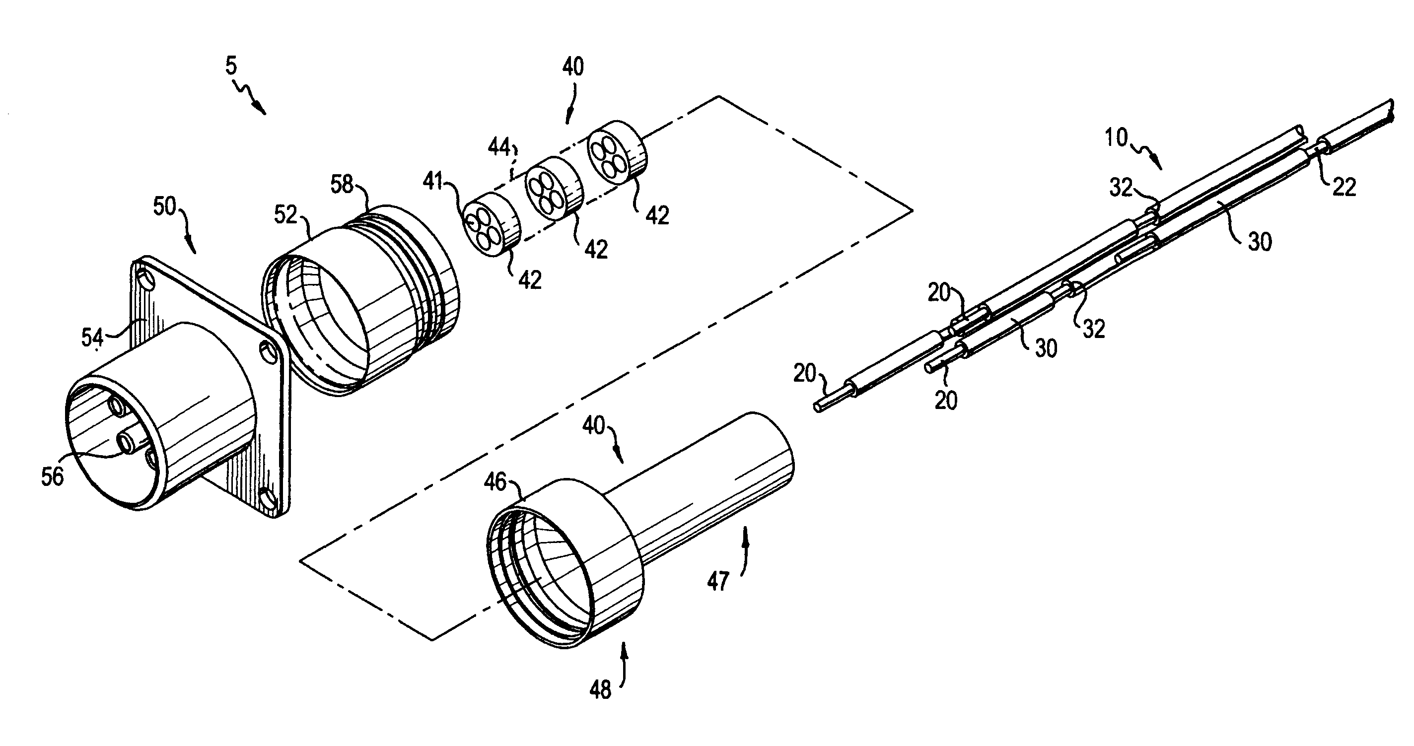
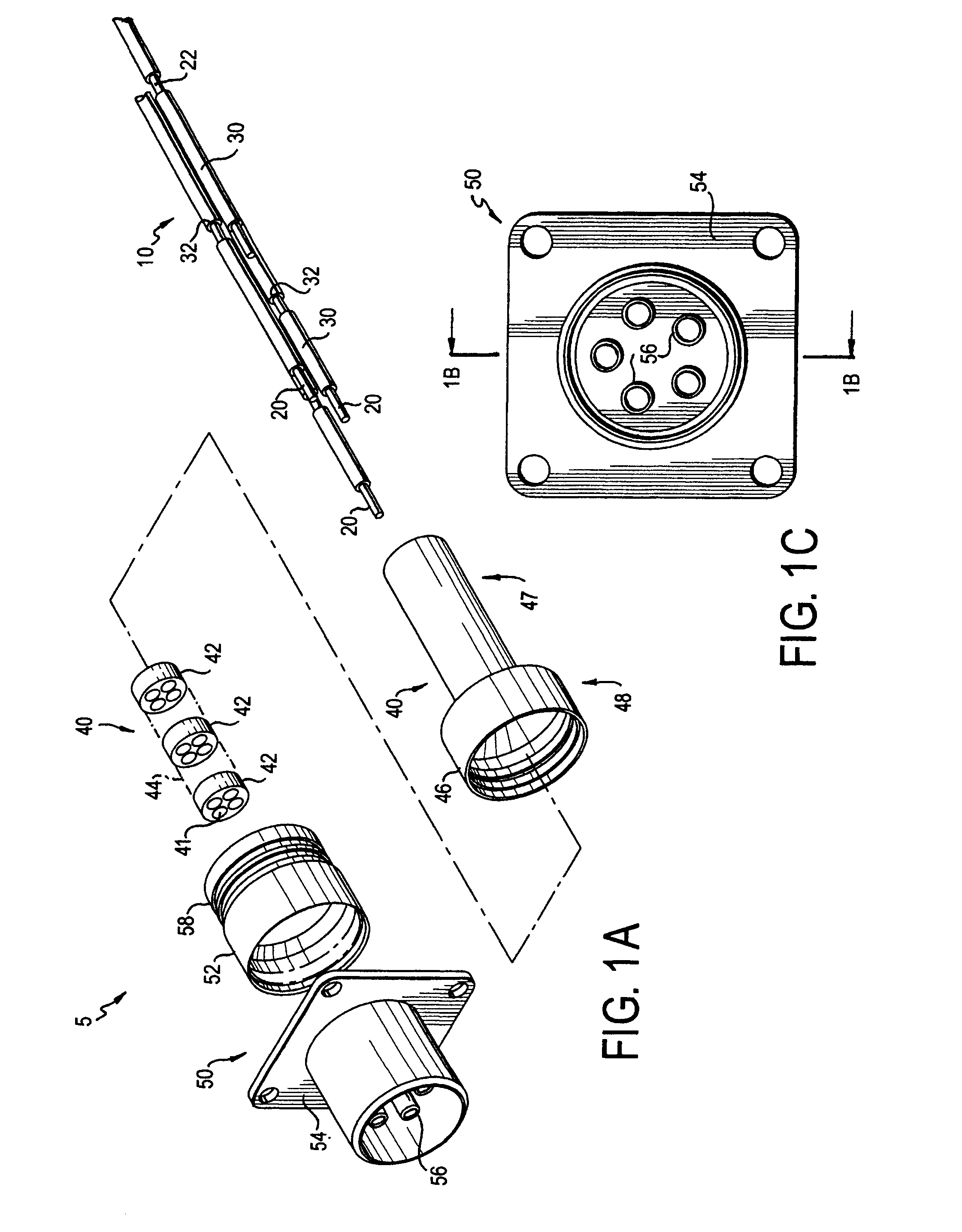
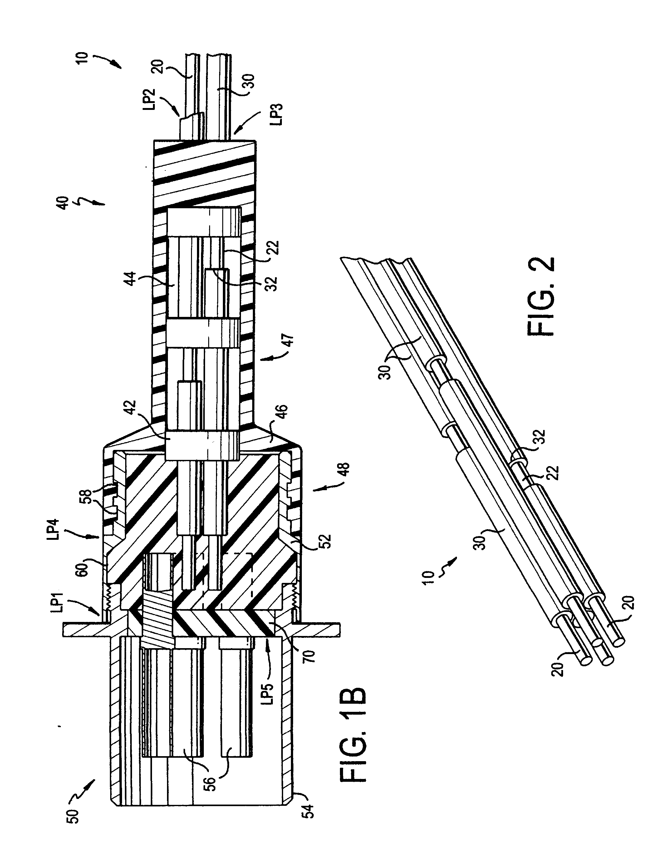
[0022]Turning first to FIGS. 1A-1C, FIG. 1A shows an exploded view of a cable assembly 5 in accordance with a preferred embodiment of the invention. FIG. 1B shows a lengthwise cross-sectional view of a portion of the cable assembly 5, the cross-section taken along the line 1B-1B in FIG. 1C. FIG. 1C shows a front view of the connector 50 viewed from its mating end. The remainder of the cable 10 is behind the connector 50 and therefore not visible in FIG. 1C.

[0023]With continued reference to FIGS. 1A-1C, the cable assembly 5 includes a cable 10, an overmold 40, and a connector 50. The cable 10 connects to the connector 50, and is covered by the overmold 40. The cable 10 includes wires 20 formed of electrically conductive material, and insulative wire jackets 30. Each individual wire 20...


PUM

PropertyMeasurementUnit
Adhesion strengthaaaaaaaaaa
Electrical conductoraaaaaaaaaa

Abstract

A cable assembly configured to prevent the wicking of fluid inside the cable assembly and method for producing same. The assembly includes at least one wire surrounded by an insulative wire jacket. A portion of the wire jacket is removed to expose a portion of the wire. The at least one wire is overmolded with a material that adheres to the wire jacket and the exposed portion of the wire, thereby preventing the wicking of fluid along the inside and outside surfaces of the wire jacket. Solder may be applied to the exposed portion of the wire, thereby providing a fluid barrier within the wire in instances in which the wire is stranded.

Description

BACKGROUND OF THE INVENTION[0001]1. Field of the Invention[0002]The present invention relates to electrical cable assemblies. In particular, the present invention relates to an electrical cable assembly for use in a fuel pump assembly, wherein the cable assembly is configured to prevent damage or malfunction resulting from fluid entering an end of the cable and wicking through the inside, or along the outside, of the cable conductor jackets.[0003]2. Description of the Related Art[0004]Generally, in any type of aircraft that incorporates a fuel pump, a fuel pump cable is used to provide power or control signals to the fuel pump. The cable may include a plurality of individual electrically conductive wires. The individual wires are typically covered with insulative material to provide electrical isolation between the wires, prevent injury, and to protect the wires from elements of their surrounding environment. For instance, the fuel pump cable has a first one of its ends (proximal en...

Claims


Application Information

Patent Timeline
IPC IPC(8): G02B6/44H01B7/00B23K31/02H01B3/44B28B1/30B05D5/12H01B3/00H02G15/04
CPCG02B6/3887G02B6/4444G02B6/4471B23K2201/38H01B1/026B23K1/0008H02G15/046B23K2101/38G02B6/3888G02B6/44775
Inventor ROLAND, CAREY S.
Owner AMPHENOL CORP
Why Eureka
Try Eureka