Microfabricated structures for facilitating fluid introduction into microfluidic devices

Inactive Publication Date: 2006-12-21
APPL BIOSYSTEMS INC
View PDF46 Cites 4 Cited by
  • Summary
  • Abstract
  • Description
  • Claims
  • Application Information

AI Technical Summary

Benefits of technology

[0009] The present invention overcomes at least some of the deficiencies of known structures and methods for introducing fluids into microfluidic substrates. In some embodiments, fluid introduction can be facilitated through the use of a port which extends entirely through the substrate structure. Capillary forces can be used to retain the fluid within such a through-hole port, rather than relying on gravity to hold the fluid within a cup-like blind hole. A series of samples or other fluids may be introduced through a single through-hole port by sequentially blowing the fluid out of the port, and replacing the removed fluid with different fluid. Advantageously, an arra

Problems solved by technology

As work has progressed in each of these areas, the channel size has gradually decreased while the channel network has increased in complexity, significantly enhancing the overall capabilities of microfluidic systems.
Unfortunately, work in connection with the present invent

Method used


Image

  • Microfabricated structures for facilitating fluid introduction into microfluidic devices
  • Microfabricated structures for facilitating fluid introduction into microfluidic devices
  • Microfabricated structures for facilitating fluid introduction into microfluidic devices

Examples


Embodiment Construction

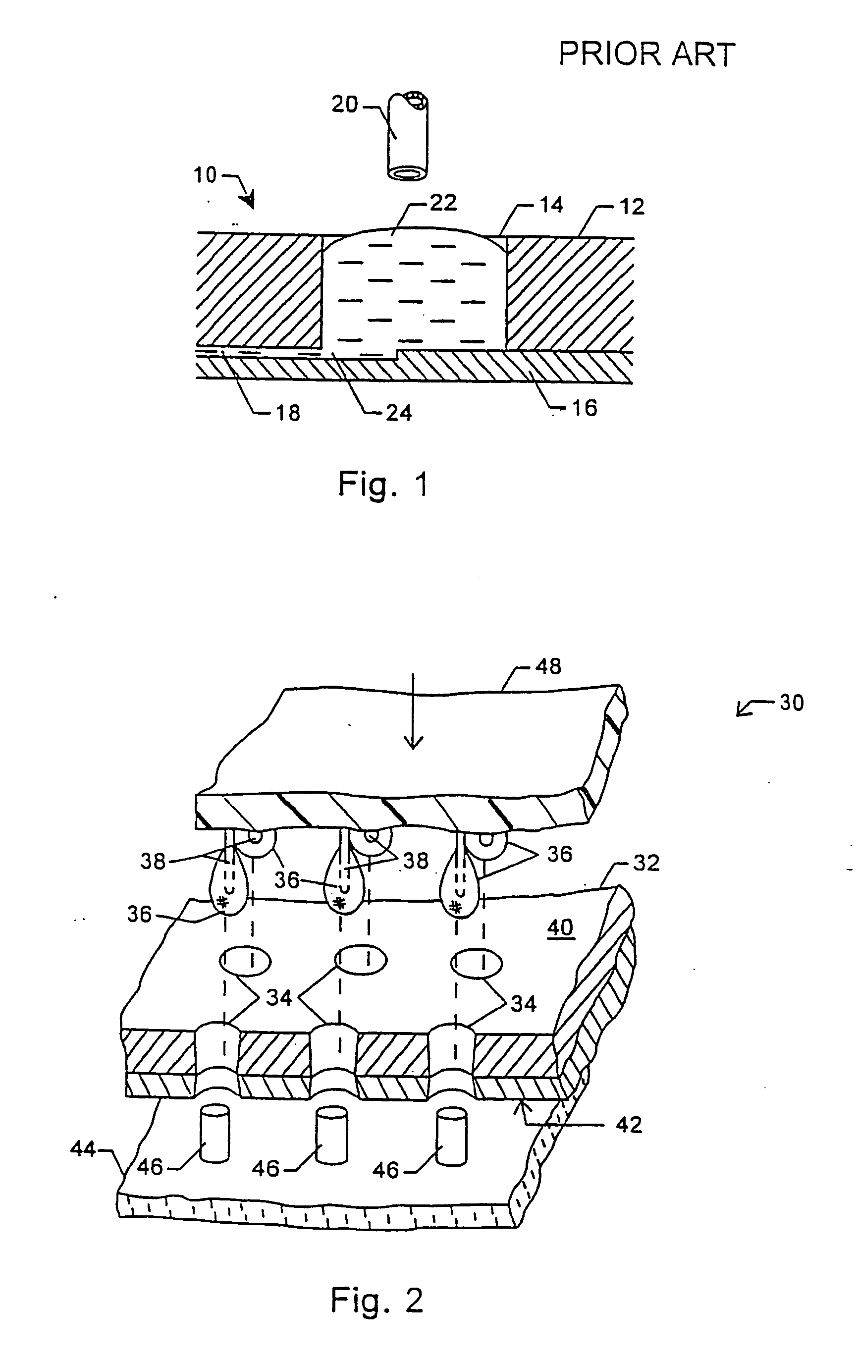
[0028] A typical microfluidic introduction system and method is schematically illustrated in FIG. 1. A substrate 10 generally comprises an upper portion 12 through which a port 14 has been drilled. A lower portion 16 is bonded to upper portion 12, the lower portion having a microfluidic channel 18 which is in fluid communication with port 14. A pipette 20 delivers fluid 22 to port 14, typically relying on pneumatic and / or hydraulic pressure to deposit the fluid in the port.

[0029] Work in connection with the present invention has identified failure modes which could prevent fluid 22 from reaching channel 18, thereby interfering with the intended operation of microfluidic substrate 10. In the first failure mode, any particles in the fluid, in the pipette, or in the port may flow with the fluid from the port toward channel 18. Particles which are not large enough to enter microfluidic channel 18 will be deposited at channel entrance 24, thereby blocking flow from the port to the chann...


PUM


Abstract

Fluid introduction is facilitated through the use of a port which extends entirely through a microfluidic substrate. Capillary forces can be used to retain the fluid within the port, and a series of samples or other fluids may be introduced through a single port by sequentially blowing the fluid out through the substrate and replacing the removed fluid with an alternate fluid, or by displacing the fluid in part with additional fluid. In another aspect, microfluidic substrates have channels which varying in cross-sectional dimension so that capillary action spreads a fluid only within a limited portion of the channel network. In yet another aspect, the introduction ports may include a multiplicity of very small channels leading from the port to a fluid channel, so as to filter out particles or other contaminants which might otherwise block the channel at the junction between the channel and the introduction port.

Description

CROSS-REFERENCE TO RELATED APPLICATIONS [0001] This application is a continuation of U.S. patent application Ser. No. 10 / 208,297 filed on Jul. 30, 2002, which is a divisional of U.S. patent application Ser. No. 09 / 539,671 filed on Mar. 30, 2000, now U.S. Pat. No. 6,451,188, which is a divisional of U.S. patent application Ser. No. 08 / 870,944 filed on Jun. 6, 1997, now U.S. Pat. No. 6,090,251. The disclosures of the above applications are incorporated herein by reference.BACKGROUND OF THE INVENTION [0002] The present invention relates generally to microfluidic systems and devices and methods for their use. More particularly, the present invention provides structures and methods which facilitate the introduction of fluids into devices having microfluidic channels. [0003] Considerable work is now underway to develop “microfluidic” systems, particularly for performing chemical, clinical, and environmental analysis of chemical and biological specimens. The term microfluidic refers to a s...

Claims


Application Information

Patent Timeline
IPC IPC(8): B01L3/02B01J19/00B01L3/00G01N27/447G01N35/00G01N35/10
CPCB01J19/0093Y10T436/2575B01J2219/00826B01J2219/00831B01J2219/00833B01J2219/00853B01J2219/00891B01J2219/00909B01L3/0244B01L3/0262B01L3/5025B01L3/50255B01L3/5027B01L3/502715B01L3/502723B01L3/50273B01L3/502753B01L2200/027B01L2300/0681B01L2300/0816B01L2300/0819B01L2300/0864B01L2400/0406B01L2400/0418B01L2400/0421B01L2400/0487B01L2400/0688G01N27/44743G01N27/44791G01N2035/00237G01N2035/1037Y10T436/25375Y10T436/25125B01J2219/00783
Inventor SUNDBERG, STEVEN A.PARCE, J. WALLACECHOW, CALVIN Y.H.
Owner APPL BIOSYSTEMS INC
Why Eureka
Try Eureka