Toner

a technology of toner and spherical paper, applied in the field of toner, can solve the problems of reducing the degree of gloss due to paper penetration, narrowing the fixing temperature range, and lack of elasticity, and achieves the effects of broad fixing latitude, excellent sharp melt properties, and advantageous low-temperature fixability

Active Publication Date: 2013-05-23
CANON KK
View PDF3 Cites 7 Cited by
  • Summary
  • Abstract
  • Description
  • Claims
  • Application Information

AI Technical Summary

Benefits of technology

[0017]The invention is able to provide a toner which contains a resin having crystalline segments of excellent sharp melt properties that is advantageous for low-temperature fixability, yet which has a broad fixing latitude in low-temperature to high-temperature regions and also has a high toner heat-res

Problems solved by technology

However, when a crystalline polyester is used alone as the toner binding resin, the toner has a sharp melting property, but lacks elasticity at elevated temperatures, as a result of which hot offset and a decrease in the degree of gloss due to penetration into the paper may arise and the fixing temperature range may narrow.
Hence, in continuous image formation under a low-temperature environment in a printer, offset and uneven gloss have tended to arise, preventing stable images from being obtained.
However, in such cases, the sharp melt properties of the crystalline polyester are not fully exhibited, making it impossible to fully manifest the effects on the low-temperature fixability.
However, even in cases where toners containing such block polymers are

Method used


Image

  • Toner
  • Toner
  • Toner

Examples


example 1

Toner Particle 1 (Before Treatment) Production Step

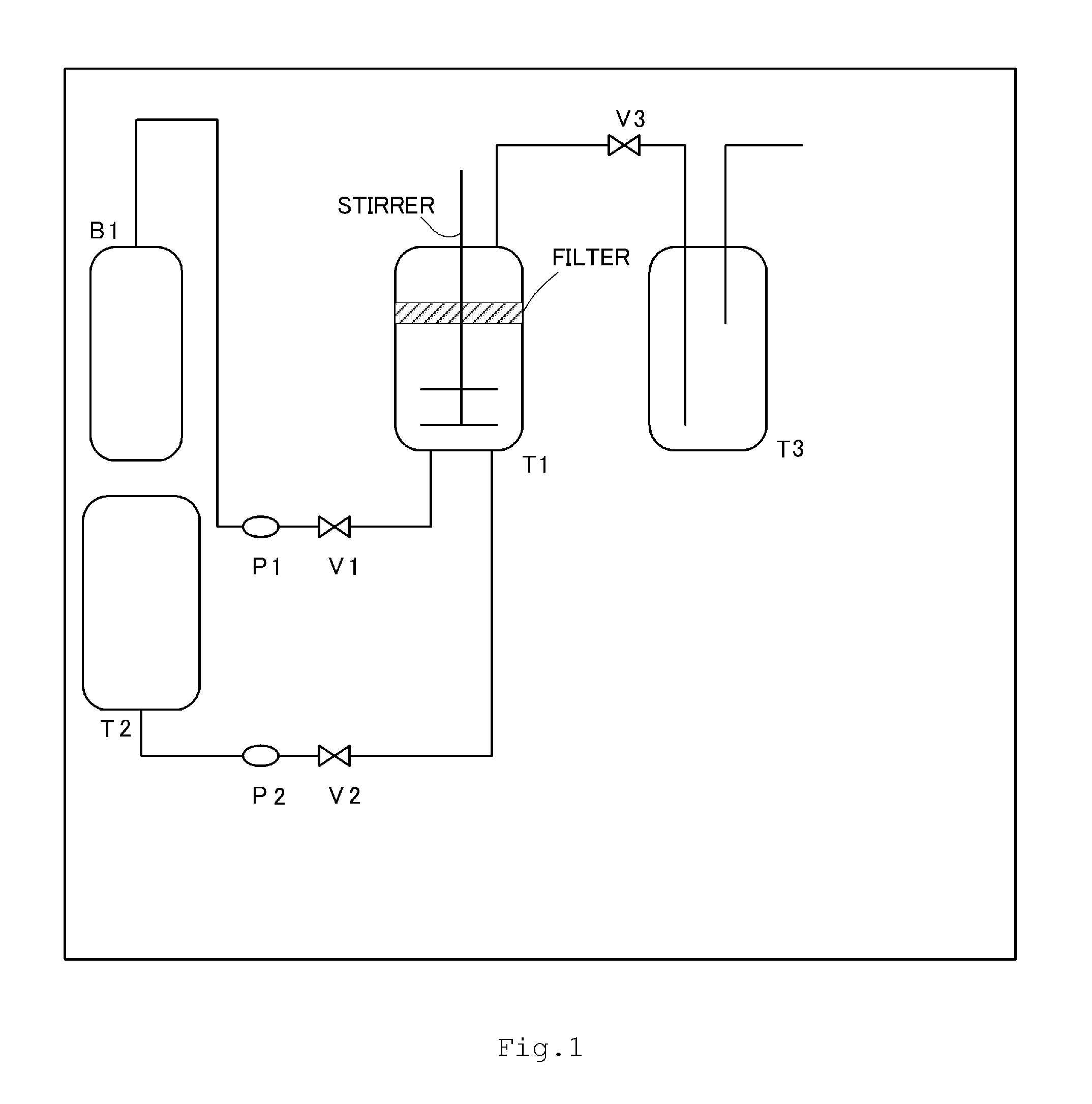
[0265]In the experimental apparatus in FIG. 1, first valves V1 and V2 and pressure regulating valve V3 were closed, Resin Fine Particle Dispersion 1 (referred to in Table 4 as “Resin Fine Particles—1”) was charged into a pressure-resistant granulation tank T1 equipped with a filter for collecting toner particles and a stirring mechanism, and the internal temperature was adjusted to 30° C. Next, valve V1 was opened and, using pump P1, carbon dioxide (purity, 99.99%) was introduced from cylinder B1 into the pressure-resistant tank T1. When the internal pressure reached 5 MPa, the valve V1 was closed.

[0266]Separately, Block Polymer Resin Solution 1, Wax Dispersion 1, Colorant Dispersion 1 and acetone were charged into a resin solution tank T2, and the internal temperature was adjusted to 30° C.

[0267]Next, valve V2 was opened and, while stirring the interior of the granulation tank T1 at 2,000 rpm, the contents of the resin solution tan...

examples 2 to 24

[0334]Aside from selecting the block polymer resin solution and the wax dispersion so that the block polymer and wax in the Toner Particle 1 (before treatment) production step become the block polymer and wax shown in Table 4, Toners 8 to 30 were obtained in the same way as in Example 1. The toner production conditions and properties are shown in Tables 4 and 5. The results of evaluations are shown in Table 6.

[0335]In Toners 9, 11, 17 and 20 according to Examples 3, 5, 11 and 14, on the toner endothermic quantity curves, the endothermic peak for wax overlapped with the maximum endothermic peak from the binder resin. As a result, in each of these cases, the value obtained by subtracting the endothermic quantity for wax from the endothermic quantity for the maximum endothermic peak was determined as the endothermic quantity for the maximum endothermic peak from the binder resin. Also, in toners 1, 2, 5, 11 to 15, 17 to 28 and 30 according to examples of the invention, on the toner end...


PUM


Abstract

Provided is a toner containing toner particles, each of which includes a binder resin containing a polyester as a main component, a colorant, and a wax, in which the binder resin includes a block polymer in which a segment capable of forming a crystalline structure and a segment incapable of forming a crystalline structure are bonded, the toner has a maximum endothermic peak from the binder resin, as determined by differential scanning calorimetry measurement, with a peak temperature in a specific range and with an endothermic quantity in a specific range, and the wax is an ester wax having a functionality of 3 or more.

Description

BACKGROUND OF THE INVENTION[0001]1. Field of the Invention[0002]The present invention relates to a toner for use in an image-forming method which utilizes electrophotographic technology, electrostatic recording technology or toner jet recording technology.[0003]2. Description of the Related Art[0004]How to implement energy savings in electrophotographic equipment has become a major technical concern in recent years. One solution has been to cut down markedly on the quantity of heat applied to the fixing apparatus. This has led to an increased need in toners for “low-temperature fixability” which enables fixing to occur at a lower energy.[0005]One method that is known to be effective for enabling fixing to occur at lower temperatures is to make the binder resin sharper melting. It is in this connection that toners which use crystalline polyester resins have been proposed. Because crystalline polyesters, owing to the arrangement of the molecular chain, do not exhibit a distinct glass ...

Claims


Application Information

Patent Timeline
IPC IPC(8): G03G9/087G03G9/08
CPCG03G9/0802G03G9/08755G03G9/08764G03G9/08788G03G9/08795G03G9/0821G03G9/08782G03G9/08797G03G9/0804G03G9/08G03G9/087
Inventor KAYA, TAKAAKIKINUMATSU, TETSUYAMORI, TOSHIFUMIOKAMOTO, AYAKOAOKI, KENJIWATANABE, SHUNTAROTANI, ATSUSHIKASUYA, TAKASHIGE
Owner CANON KK
Why Eureka
Try Eureka