Optical disk array device

an optical disk array and optical disk technology, applied in the field of data storage, can solve the problems of rf signal, rf signal, and reproducible data errors, and achieve the effect of continuously reproducing data and small maximum probability of read errors

Inactive Publication Date: 2013-05-23
PANASONIC INTELLECTUAL PROPERTY MANAGEMENT CO LTD
View PDF9 Cites 4 Cited by
  • Summary
  • Abstract
  • Description
  • Claims
  • Application Information

AI Technical Summary

Benefits of technology

[0042]According to the present invention, the smallest logical sector number of an optical disk is assigned to a physical sector number that is different from a physical sector number to which the smallest logical sector number of at least another optical disk is assigned. As a result, data in the same stripe is allowed to be recorded to sectors at mutually different physical sector numbers of the plurality of optical disks. As used herein, a stripe is a unit by which data can be restored with redundancy. In RAID1, a stripe is a smallest structural unit by which the same data can be independently recorded or reproduced. In RAID4 or RAID5, a striped is a smallest structural unit composed of a group of data which can be independently recorded or reproduced and a parity thereof. With the above features, the probability of occurrence of read errors due to interferences of adjacent guide grooves and / or insufficient formation of guide grooves can be leveled out, and the maximum probability of read errors can be kept small.
[0043]Moreover, according to the present invention, even upon switching between recording layers or when changing optical disks, it is possible to continuously reproduce data without having to wait.

Problems solved by technology

In an optical disk, errors may occur in the reproduced data owing to various stress factors, such as stress associated with the removable medium or stress associated with the fabrication process.
Factors causing errors may be scratches or soil on the optical disk, quality at recording, degradation over time, and the like.
Moreover, a recordable-type optical disk has meandering guide grooves and / or prepits previously formed thereon for rotation synchronization and address confirmation at data recording, and these may affect the RF signal and cause errors.
Moreover, interferences of adjacent guide grooves and / or insufficient formation of guide grooves may also affect the RF signal.

Method used


Image

  • Optical disk array device
  • Optical disk array device
  • Optical disk array device

Examples


embodiment 1

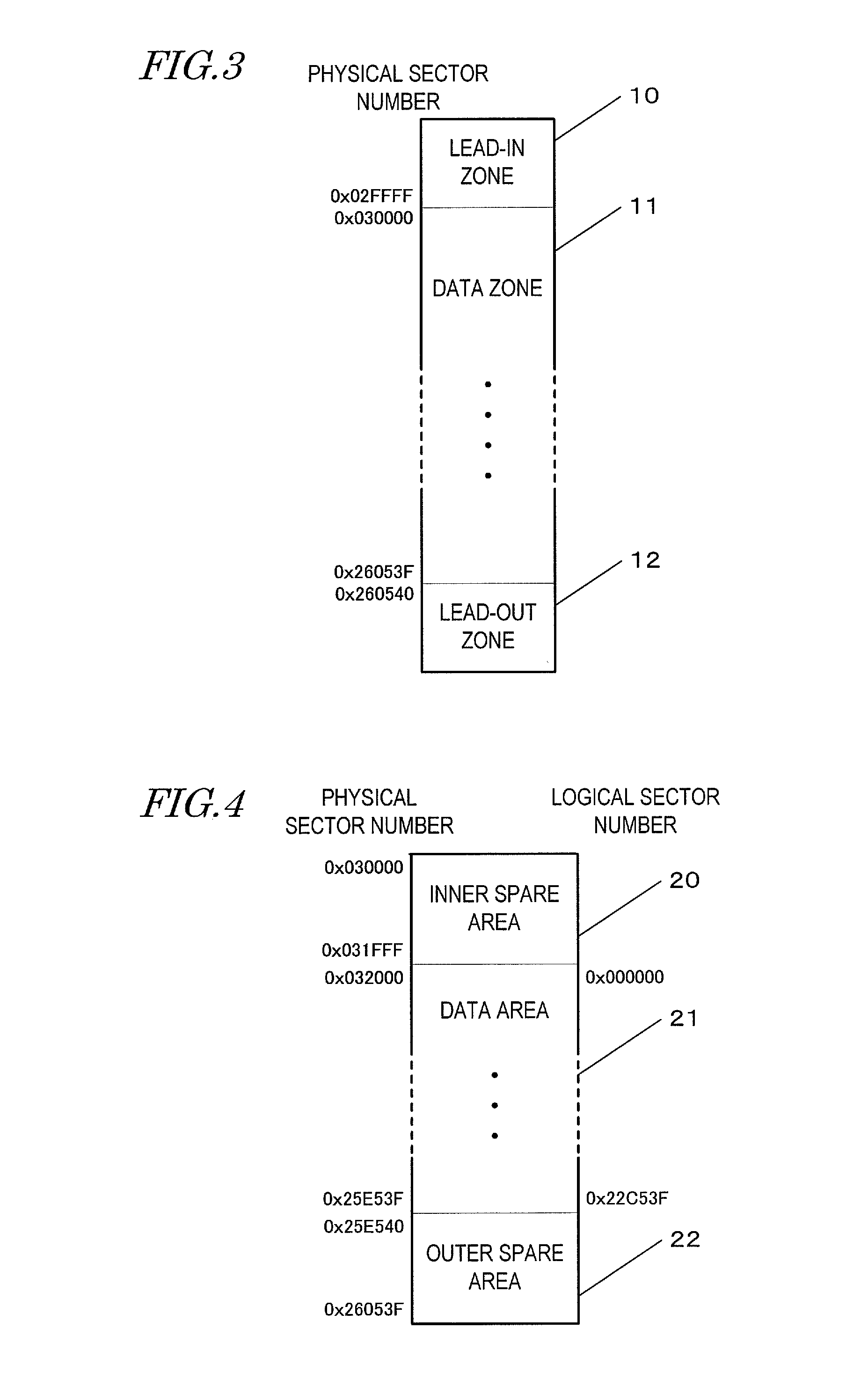
[0071]FIG. 3 is a diagram for describing the format of an optical disk according to Embodiment 1 of the present invention. The optical disk includes a lead-in zone 10, a data zone 11, and a lead-out zone 12. FIG. 4 is a diagram for describing the format of the data zone 11 according to Embodiment 1 of the present invention. The data zone 11 includes an inner spare area 20, a data area 21, and an outer spare area 22. The inner spare area 20 is exemplary of a spare area that is located closer to the leading end than is the data area 21 along the direction of track recording / reproduction. The outer spare area 22 is exemplary of a spare area that is located closer to the trailing end than is the data area 21 along the direction of track recording / reproduction.

[0072]The lead-in zone 10 includes test areas for performing tests at production of the optical disk and upon recording in a drive, a management area in which to record management information concerning the format of the data zone ...

embodiment 2

[0106]A case will be described where, in the construction of Embodiment 1 described above, the optical disk 36 and the optical disk 37 are of the same lot manufactured by company A, while the optical disk 38 and the optical disk 39 are of the same lot manufactured by company B.

[0107]When receiving from an external device a command to initialize the optical disk array, the controller 30 issues a command to acquire disk information to the drives 36 to 39, and acquires manufacturer numbers and revision numbers of the optical disks 36 to 39. Based on the acquired manufacturer numbers and revision numbers, the controller 30 designates sizes of inner spare areas 20 of the optical disks 36 to 39 for the drives 31 to 34. The drives 31 to 34 format the optical disks 36 to 39 so that the sizes of their inner spare areas 20 are sizes as designated by the controller 30.

[0108]It is assumed herein that the optical disk 36 and the optical disk 37 are of the same manufacturer number and the same re...

embodiment 3

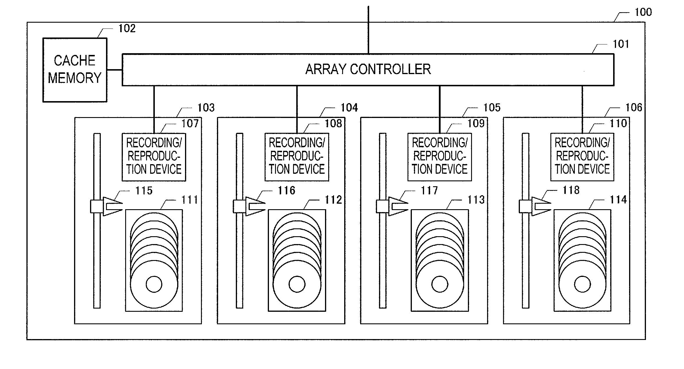
[0132]Embodiment 3 of the present invention will be described with reference to FIG. 11. FIG. 11 is a block diagram showing the construction of an optical disk array apparatus 65 according to Embodiment 3 of the present invention. The optical disk array apparatus 65 includes a controller 60 and drives 61 to 64. Optical disks 66 to 69 are mounted in the drives 61 to 64. The aggregate of optical disks 66 to 69 will be referred to as an optical disk array.

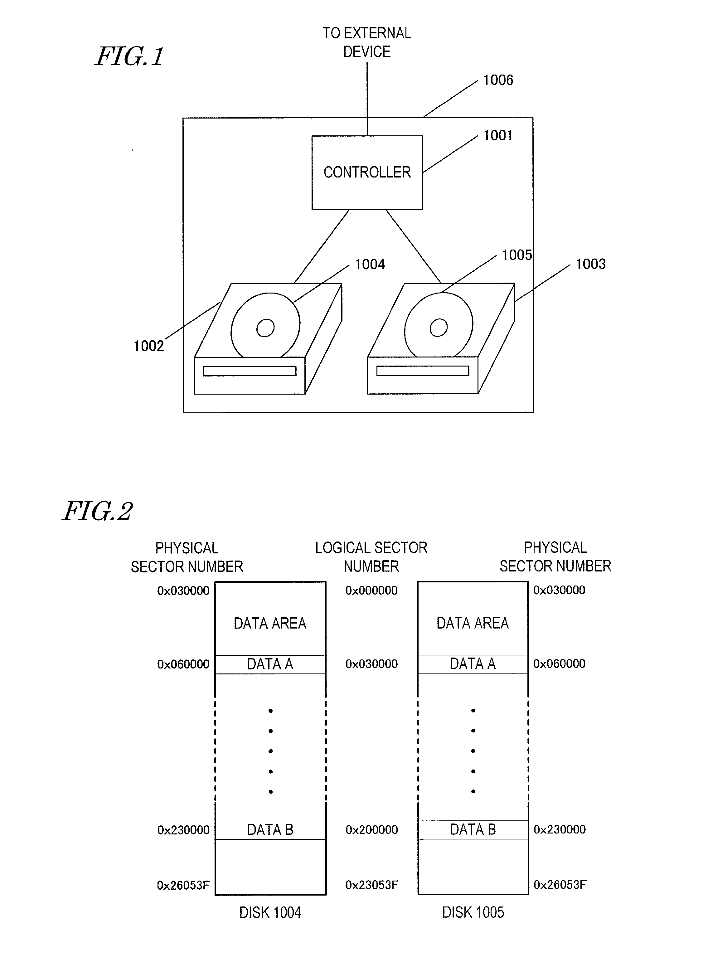
[0133]The optical disk array apparatus 65 is connected to an external device (not shown) via the controller 60, so that the whole functions as RAID4. For any recording data which is input from the external device, the controller 60 determines, on the basis of a logical address, a drive and a logical sector number to which it is to be recorded, and issues a recording command to the corresponding drive 61 to 63. Furthermore, a recording command for parity data, which is generated from the recording data that is input from the external d...


PUM


Abstract

When RAID is constructed by using optical disks of the same lot, there is a problem in that the reproduction error probability of the RAID may have local increases over the reproduction error probability within the optical disks. According to the present invention, among a plurality of optical disks constituting an optical disk array, the smallest logical sector number is assigned to mutually different physical sector numbers. As a result, data in the same stripe is allowed to be recorded to sectors at mutually different physical sector numbers of the plurality of optical disks, so that the probability of occurrence of read errors due to interferences of adjacent guide grooves and/or insufficient formation of guide grooves can be leveled out, and the maximum probability of read errors can be kept small.

Description

TECHNICAL FIELD[0001]The present invention relates to a data storage using a plurality of storage devices.BACKGROUND ART[0002]In recent years, large amounts of data are coming to be stored on storage servers via networks. At storage servers, hard disks are generally used storage devices. Since a hard disk is a storage device which is relatively susceptible to malfunctioning, reliability of the stored data is ensured by constructing RAID (Redundant Arrays of Inexpensive Disks) imparted with redundancy. For example, RAID1, RAID5, and RAID6 are in use as redundancy-imparted constructions.[0003]Moreover, in order to reduce any increase in energy consumption caused by the increasing amounts of stored data, there is a growing need for energy saving. In order to achieve these, storage servers which are capable of storing data with less energy are being desired. For example, optical disks are drawing attention as storage means that are capable of storing data with less energy than that for ...

Claims


Application Information

Patent Timeline
Patent Type & Authority Applications(United States)
IPC IPC(8): G06F3/06
CPCG06F3/0677G06F3/0689G06F3/0611G06F3/0614G06F3/0638G06F3/0644G06F11/2087G06F2211/1059G06F2211/1057G06F2211/1076G06F3/0664G06F11/1076G06F3/0686G11B20/1217
Inventor KIMURA, NAOHIROYAMAMOTO, YOSHIKAZUITO, MOTOSHI
Owner PANASONIC INTELLECTUAL PROPERTY MANAGEMENT CO LTD
Why Eureka
Try Eureka