Variable filter circuit and radio communication device

Active Publication Date: 2016-11-24
MURATA MFG CO LTD
View PDF2 Cites 3 Cited by
  • Summary
  • Abstract
  • Description
  • Claims
  • Application Information

AI Technical Summary

Benefits of technology

[0010]To increase the number of stages in the filter in such a variable filter circuit, one series arm and one parallel arm may be added, one end of the added series arm and one end of the added parallel arm may be connected to the first input/output terminal or second input/output terminal. Accordingly, when the variable filter circuit is configured so as to have n stages, the number of series arms and that of variable capacitors are n+1. The increase in the circuit size and complication of the control system can be more suppressed, in comparison with known configurations.
[0011]The variable filter circuit according to the present disclosure may further include a second inductor (hereinafter, referred to as series inductor) connected in series

Problems solved by technology

In the known variable filter circuit, the pass band can be adjusted by control of the variable capacitors, but it has difficulty in obtaining desired attenuation characteristics.
Specifically, it i

Method used


Image

  • Variable filter circuit and radio communication device
  • Variable filter circuit and radio communication device
  • Variable filter circuit and radio communication device

Examples


Example

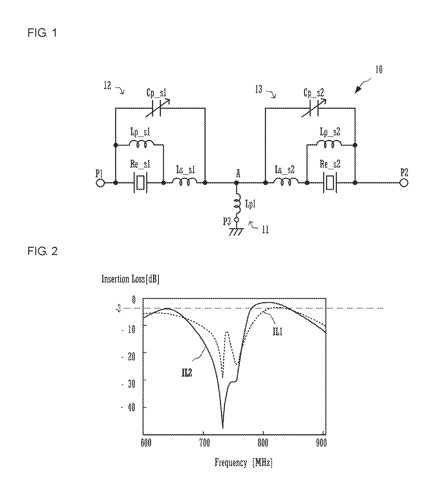
[0030]FIG. 1 is a circuit diagram that illustrates a variable filter circuit 10 according to a first embodiment of the present disclosure.

[0031]The variable filter circuit 10 includes ports P1, P2, and P3, a node A, a parallel arm 11, and series arms 12 and 13. The ports P1, P2, and P3 are connected to one another with the node A interposed thereamong. The port P1 is a first input / output terminal in the variable filter circuit 10. The port P2 is a second input / output terminal in the variable filter circuit 10. The port P3 is a ground connection terminal in the variable filter circuit 10. The parallel arm 11 is connected between the node A and port P3. The series arm 12 is connected between the node A and port P1. The series arm 13 is connected between the node A and port P2. That is, the node A is in a location where one end of the parallel arm 11, and one end of the series arm 12, and one end of the series arm 13 are connected together.

[0032]The parallel arm 11 includes a first ind...

Example

Second Embodiment

[0073]FIG. 9 is a block diagram of a radio communication device 9 according to a second embodiment.

[0074]The radio communication device 9 includes an antenna 1, a front-end circuit 2, a transmitting circuit 3, and a receiving circuit 4. The transmitting circuit 3 is configured to be able to support a plurality of communication bands in a communication system, such as LTE, and it switches a communication band to be supported and outputs a transmission signal. The receiving circuit 4 is configured to be able to support a plurality of communication bands in a communication system, such as LTE, and it switches a communication band to be supported and accepts an input of a reception signal. The front-end circuit 2 is connected between the antenna 1 and each of the transmitting circuit 3 and receiving circuit 4 and includes the variable filter circuit 10 connected to the transmitting circuit 3, a variable filter circuit 10′ connected to the receiving circuit 4, and a circ...


PUM


Abstract

A variable filter circuit (10) includes a parallel arm (11) connected between a port (P3) and node (A), a series arm (12) including a resonator (Re_s1) connected in series between a port (P1) and node (A), and a series arm (13) including a resonator (Re_s2) connected in series between a port (P2) and node (A). The parallel arm (11) includes a first inductor (Lp1). The series arms (12, 13) include variable capacitors (Cp_s1, Cp_s2) connected in parallel to the resonators (Re_s1, Re_s2).

Description

[0001]This application is a continuation of International Application No. PCT / JP2015 / 053173 filed on Feb. 5, 2015 which claims priority from Japanese Patent Application No. JP2014-023344 filed on Feb. 10, 2014. The contents of these applications are incorporated herein by reference in their entireties.BACKGROUNDTechnical Field[0002]The present disclosure relates to a variable filter circuit and a radio communication device including the variable filter circuit.[0003]A known variable filter circuit is of the ladder type in which multiple basic circuits each including variable capacitors connected in parallel and in series to a resonator, such as a SAW resonator or a BAW resonator, are combined in a multistage structure (see, for example, Patent Document 1). In this variable filter circuit, an anti-resonant frequency of each of the basic circuits is adjusted by control of the variable capacitor connected in parallel to the resonator, a resonant frequency of each of the basic circuits ...

Claims


Application Information

Patent Timeline
IPC IPC(8): H01Q1/24H03H7/01H01Q1/48H03H9/54
CPCH01Q1/243H03H9/542H03H2210/025H01Q1/48H03H7/0161H03H7/075H03H9/64
Inventor OGAMI, TAKASHI
Owner MURATA MFG CO LTD
Why Eureka
Try Eureka