Digital system for creating a flexographic printmaster

Inactive Publication Date: 2013-05-30
AGFA OFFSET BV
View PDF5 Cites 0 Cited by
  • Summary
  • Abstract
  • Description
  • Claims
  • Application Information

AI Technical Summary

Benefits of technology

[0020]In order to overcome the problems described above, preferred embodiments of the invention reduce the geometrical distortion of the matrix of cured

Problems solved by technology

A prior art system such as the one depicted in FIG. 2 and FIG. 4 suffers from an unexpected problem.
As a result it takes some time for them to reach their landing position on the rotating drum.
This results in a distortion of the three-dimensional g

Method used


Image

  • Digital system for creating a flexographic printmaster
  • Digital system for creating a flexographic printmaster
  • Digital system for creating a flexographic printmaster

Examples


Embodiment Construction

[0030]FIG. 4 shows a prior art system that is suitable for creating a relief print master and that can serve as the basis for an improved system according to preferred embodiments of the current invention.

[0031]FIG. 5 shows projections on three different orthogonal planes of the relevant portions of the prior art system in FIG. 4.

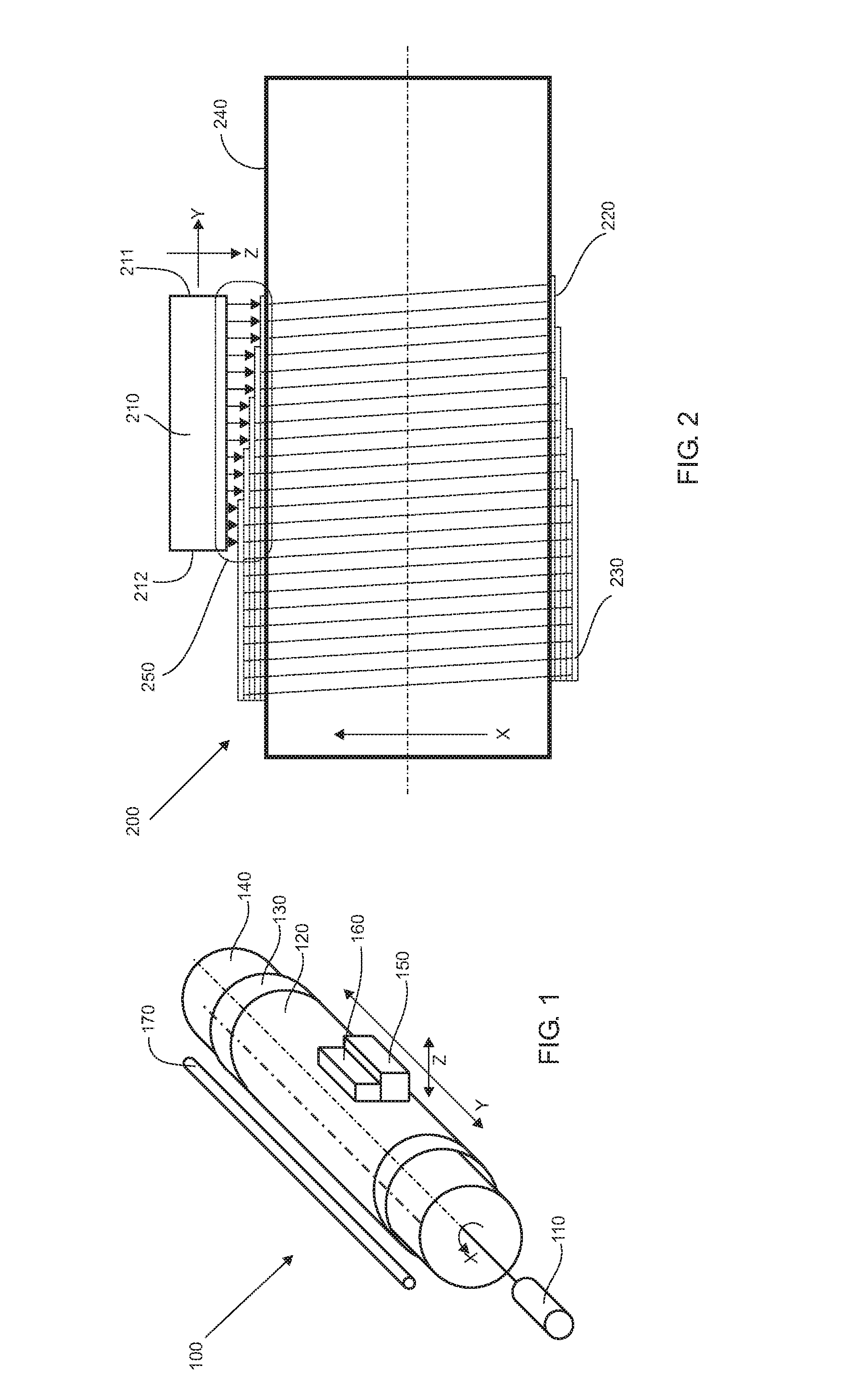
[0032]In FIG. 4 the cylindrical support 400 rotates at a frequency of NumberofRevolutionsperSecond along a central axis 470.

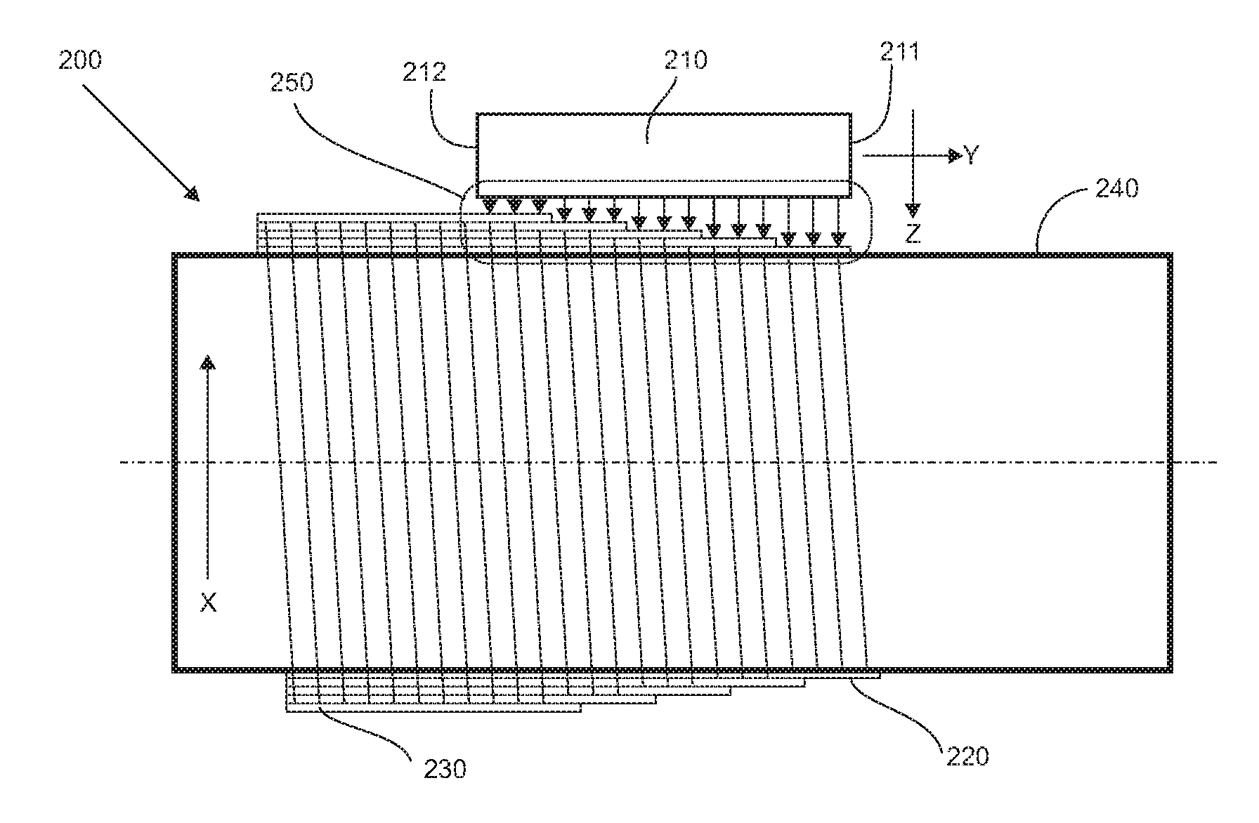
[0033]In FIGS. 4 and 5, a printhead unit 440, 520 has nozzles that are arranged on a nozzle row 530. The distance between the nozzle row 530 and the central axis of the rotating cylinder is referred to by the variable NozzlePlateDistance. In the prior art system shown in FIG. 4 and FIG. 5 the nozzle row 530 is parallel with the central axis 470 of the rotating cylindrical support 400.

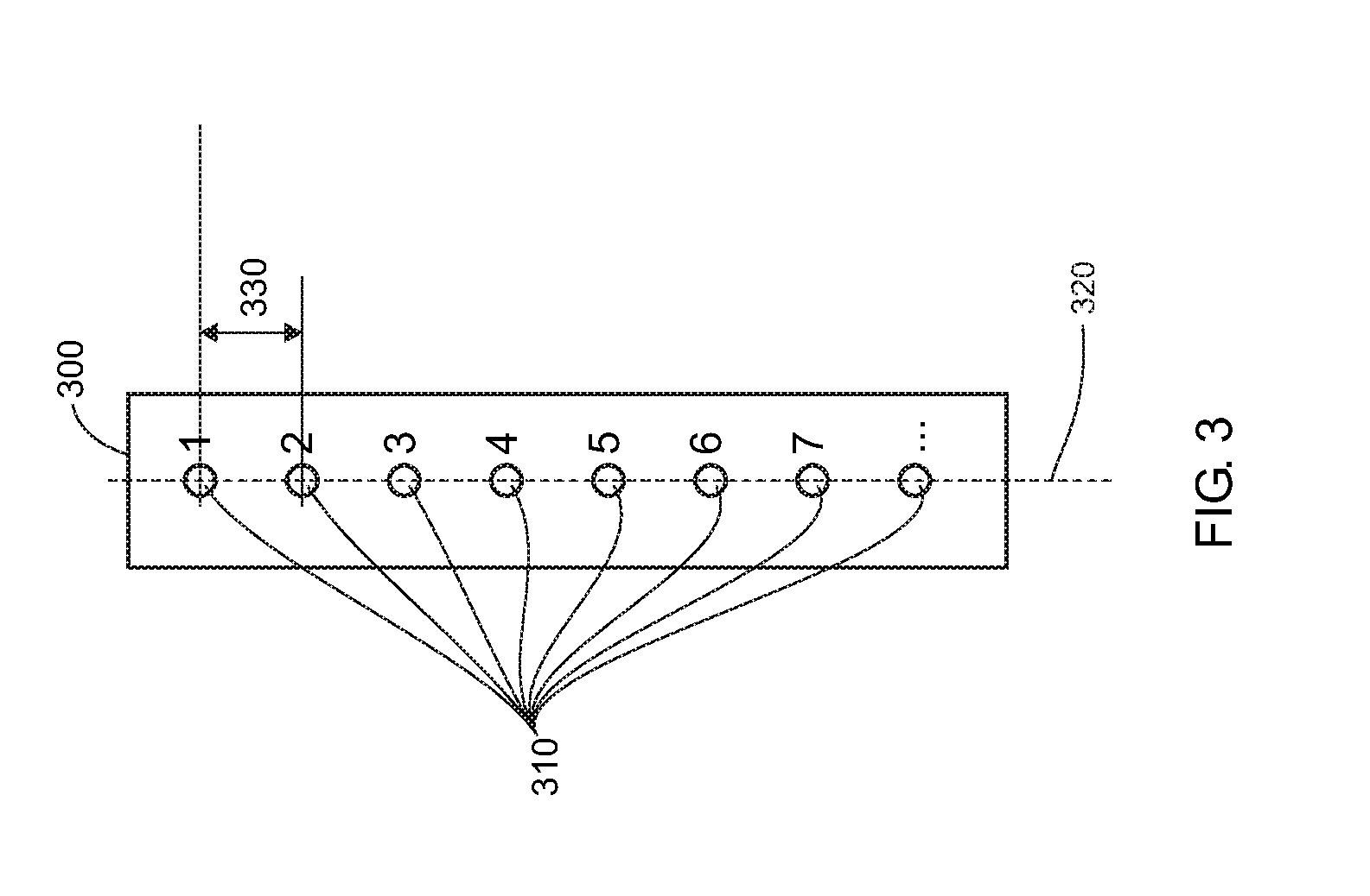
[0034]Every nozzle of the printhead has an index number j that in FIG. 4 and FIG. 5 ranges from 1 to 5. The distance between two adjacent nozzles is the n...


PUM

PropertyMeasurementUnit
Diameteraaaaaaaaaa
Distanceaaaaaaaaaa

Abstract

A relief print master is created by a printhead that moves in a slow scan direction. The nozzles of the printhead jet droplets of a polymerisable liquid on a rotating drum. The different nozzles jet droplets simultaneously on different layers that have different diameters. As a result, the droplets jetted by different nozzles travel over different distances before landing. The effect of this is that the droplets undergo different position lag as they land on the different layers. By rotating the printhead in a plane that is orthogonal to the jetting direction this effect can be compensated for.

Description

CROSS-REFERENCE TO RELATED APPLICATIONS[0001]This application is a 371 National Stage Application of PCT / EP2011 / 063625, filed Aug. 8, 2011. This application claims the benefit of U.S. Provisional Application No. 61 / 375,251, filed Aug. 20, 2010, which is incorporated by reference herein in its entirety. In addition, this application claims the benefit of European Application No. 10173538.9, filed Aug. 20, 2010, which is also incorporated by reference herein in its entirety.BACKGROUND OF THE INVENTION[0002]1. Field of the Invention[0003]The invention deals with the field of three dimensional printing, more specifically the printing of relief features on a rotating cylindrical support using a fluid depositing apparatus such as an inkjet printhead. Even more specifically, the invention deals with the field of creating a flexographic print master on a rotating drum by a depositing printhead that moves in a slow scan direction and deposits curable liquid such as a UV-curable liquid.[0004]...

Claims


Application Information

Patent Timeline
IPC IPC(8): B41C1/00
CPCB41C1/003B05C5/00B41C1/1066B41J11/002B41J19/16B41C1/18B33Y30/00B29C67/00B41C1/00
Inventor GULLENTOPS, CHRIS
Owner AGFA OFFSET BV
Why Eureka
Try Eureka