Heat sink with heat bus and fin structure

Inactive Publication Date: 2013-05-30
IBM CORP
View PDF6 Cites 11 Cited by
  • Summary
  • Abstract
  • Description
  • Claims
  • Application Information

AI Technical Summary

Benefits of technology

[0006]One embodiment of the present invention provides a heat sink comprising a fin structure having a plurality of repeating, interconnected fin cells that allow the movement of air through the fin cells, wherein the fin structure further includes a first side and a second side. The heat sink further comprises a heat bus that thermally engages a heat-generating electronic component a

Problems solved by technology

Heat sink fin structures with larger surface areas for convective heat transfer are able to dissipate more heat to s

Method used


Image

  • Heat sink with heat bus and fin structure
  • Heat sink with heat bus and fin structure
  • Heat sink with heat bus and fin structure

Examples


second embodiment

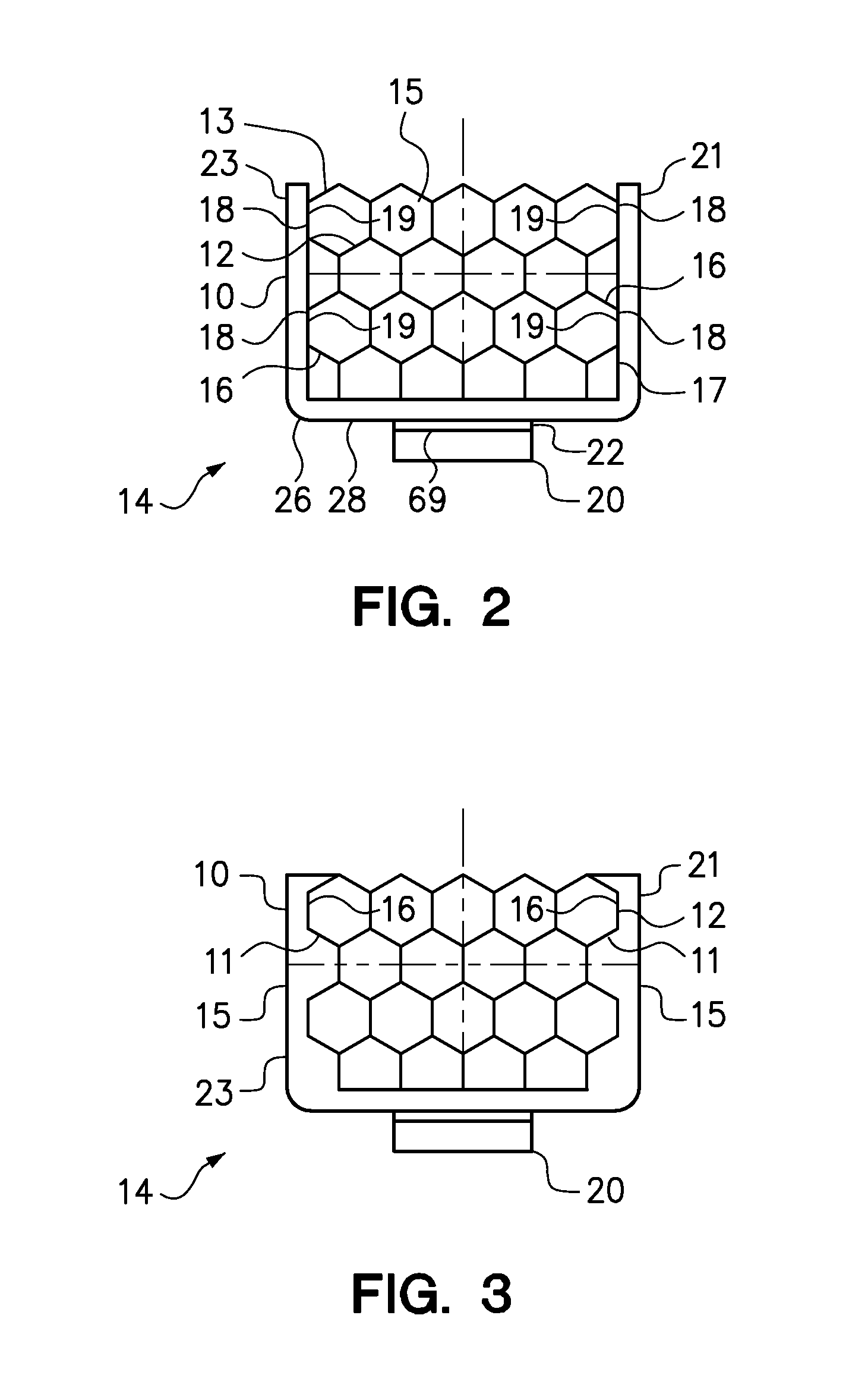
[0027]FIG. 3 is a section end view of alternate second embodiment of a heat sink 10 of the present invention, where the heat sink is secured over the processor 20. The heat sink 10 comprises a honeycomb fin structure 12 coupled to a U-shaped heat bus 14 having a first leg 21 having a first side 15 and a second side 11 that generally conforms to the side 16 of the fin structure 12 disposed adjacent to the first leg 21. The U-shaped heat bus 14 further comprises a second leg 23 having a first side 15 and a second side 11 that generally conforms to the side 16 of the fin structure 12 adjacent to the second leg 23. The second sides 11 of the first leg 21 and the second leg 23 of the embodiment of the U-shaped heat bus 14 of FIG. 3 are in generally uninterrupted contact with the sides 16 of the fin structure 12, and perhaps generally continuously connected to the sides 16, to enhance conductive heat transfer from the first leg 21 and the second leg 23 of the U-shaped heat bus 14 to the f...

third embodiment

[0028]FIG. 4 is a perspective view of a heat sink 10 of the present invention comprising a honeycomb fin structure 12 coupled to a U-shaped heat bus 14 having a base 26, a plurality of first legs 21 and a plurality of second legs 23 (partially shown) along the opposing side of the fin structure. The first legs 21 and the second legs 23 are connected to the landings 19 on the sides 16 of the fin structure 12 by connections 18 to further enhance distribution of heat from the processor (not shown), through the base 26 and the first legs 21 and second legs 23 of the heat bus 14 to the fin structure 12. The first legs 21 are illustrated in FIG. 4 as being parallel and generally equally spaced along the length of the fin structure 12 between the inlet end 24 and the outlet end 25 of the air channels 15 therein.

fourth embodiment

[0029]FIG. 5A is a perspective view of a heat sink 10 of the present invention comprising a honeycomb fin structure 12 coupled to a U-shaped heat bus 14 having a base 26, a first leg 21 having a width 48 and a second leg 23 (partially shown) extending from the base 26 and connected to landings 19 on the fin structure 12 by connections 18. The first leg 21 and the second leg 23 of the heat bus 14 shown in FIG. 5A have a broad profile or width 48 to further enhance distribution of heat from the processor (not shown), through the base 26 and the first leg 21 and second leg 23 of the heat bus 14 to the fin structure 12. It will be understood that other embodiments of the heat sink 10 may comprise a heat bus 14 having a first leg and a second leg that are as wide (dimension 48) as the fin structure 10 is long from the inlet end 24 to the outlet end 25.

[0030]FIG. 5B is a perspective view of a modified fourth embodiment of the heat sink 10 of FIG. 5A comprising a honeycomb fin structure 12...


PUM


Abstract

A heat sink to remove heat from a processor within a chassis to air moving through a fin structure on the heat sink. An embodiment of the heat sink comprises a heat bus engaging the processor to conduct heat from the processor to a fin structure having interconnected, repeating cellular air channels. A U-shaped heat bus comprises a base and first and second legs extending therefrom connected to opposite sides of the fin structure. An embodiment of the heat bus has a solid conductive core to conductively transfer heat from the processor through the base and the first and second legs to sides of the fin structure. Alternately, an embodiment of the heat bus has a hollow core containing a fluid to evaporatively transfer heat from the processor through the base and the first and second legs to sides of the fin structure.

Description

BACKGROUND[0001]1. Field of the Invention[0002]The present invention relates to heat sinks to remove heat from heat-generating electronic devices, such as computer processors.[0003]2. Background of the Related Art[0004]Computer systems often rely on heat sinks positioned on heat-generating electronic components, such as processors, to maintain performance of the component by removing heat and thereby maintaining a favorable operating temperature. Heat sinks generally conduct heat generated by a component to fins where the heat is transferred into an air flow across the surface area of the fins. Heat sinks are available with several types of air-cooled fins including pin fins, straight fins, folded fins, flared fins and extruded fins. With increasing processor power densities, more heat is generated by processors disposed within the limited space of the computer chassis. It is important that the heat sink is sufficient to maintain the performance of the processor and still fit with t...

Claims


Application Information

Patent Timeline
IPC IPC(8): F28F13/00F28F7/00
CPCH01L23/367H01L23/467H01L2924/0002H01L2924/00
Inventor GLOVER, TROY W.JUNE, MICHAEL S.KOCHUPARAMBIL, BEJOY J.NI, CHUNJIANRAMINENI, PRADEEPSCOTT, III, WHITCOMB R.
Owner IBM CORP
Why Eureka
Try Eureka