
Motor control apparatus for synchronously controlling master axis and slave axis

Active Publication Date: 2013-05-30
FANUC LTD
View PDF4 Cites 17 Cited by
  • Summary
  • Abstract
  • Description
  • Claims
  • Application Information

AI Technical Summary

Benefits of technology

The present invention aims to provide a motor control apparatus that can accurately synchronize the movement of a master axis motor and a slave axis motor. The goal is to create a small and affordable solution for controlling the movement of motorized components.

Problems solved by technology

As a result, the following problem occurs.
Furthermore, since the prior art master-slave synchronizing method requires the provision of a branch circuit, the cost and size of the motor control apparatus correspondingly increase.

Method used


Image

  • Motor control apparatus for synchronously controlling master axis and slave axis
  • Motor control apparatus for synchronously controlling master axis and slave axis
  • Motor control apparatus for synchronously controlling master axis and slave axis

Examples


Embodiment Construction

[0033]A motor control apparatus for synchronously controlling a master axis and a slave axis will be described below with reference to the drawings. It should, however, be understood that the present invention is not limited to the accompanying drawings, nor is it limited to the particular embodiment described herein.

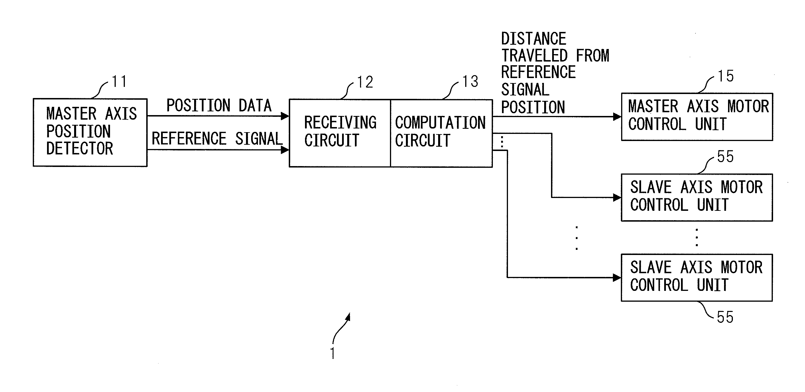
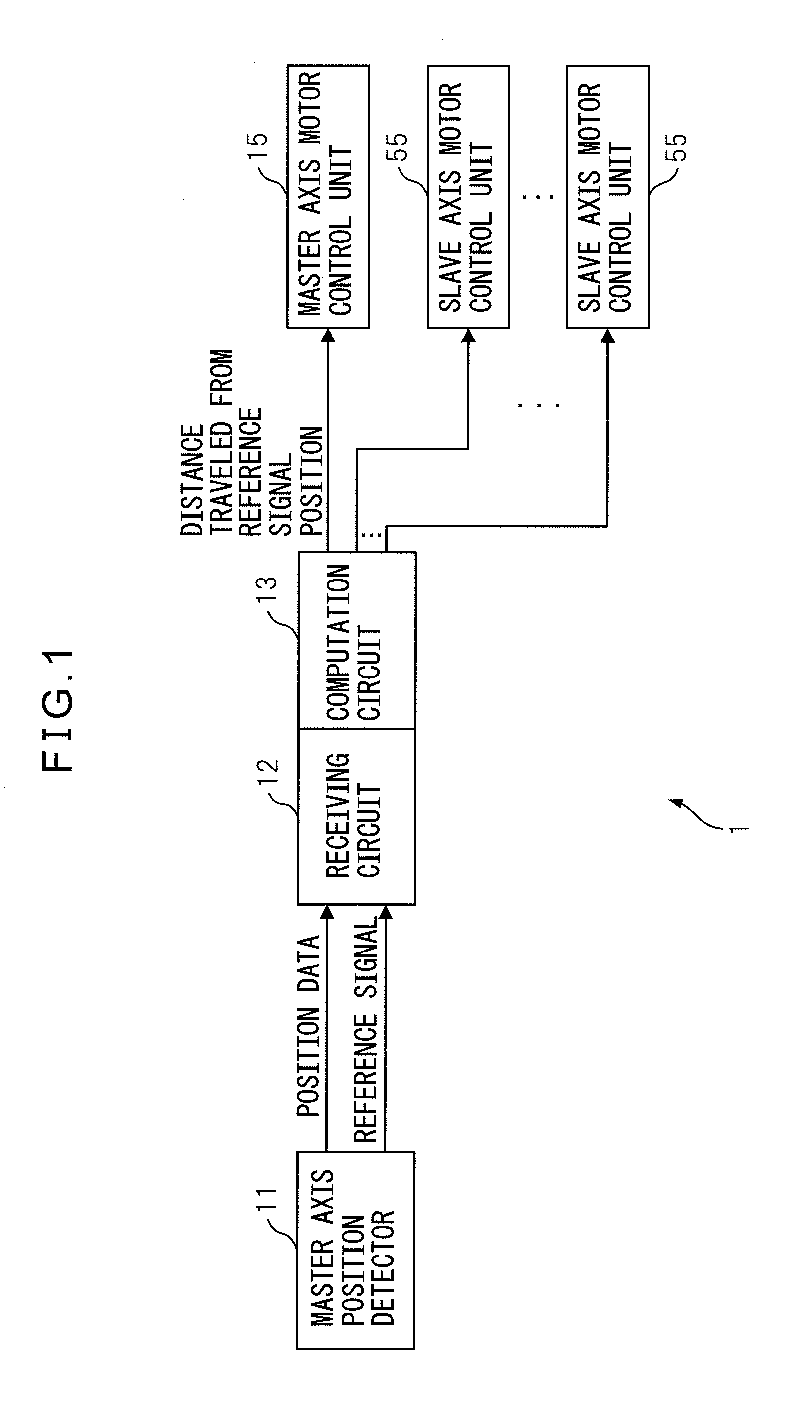
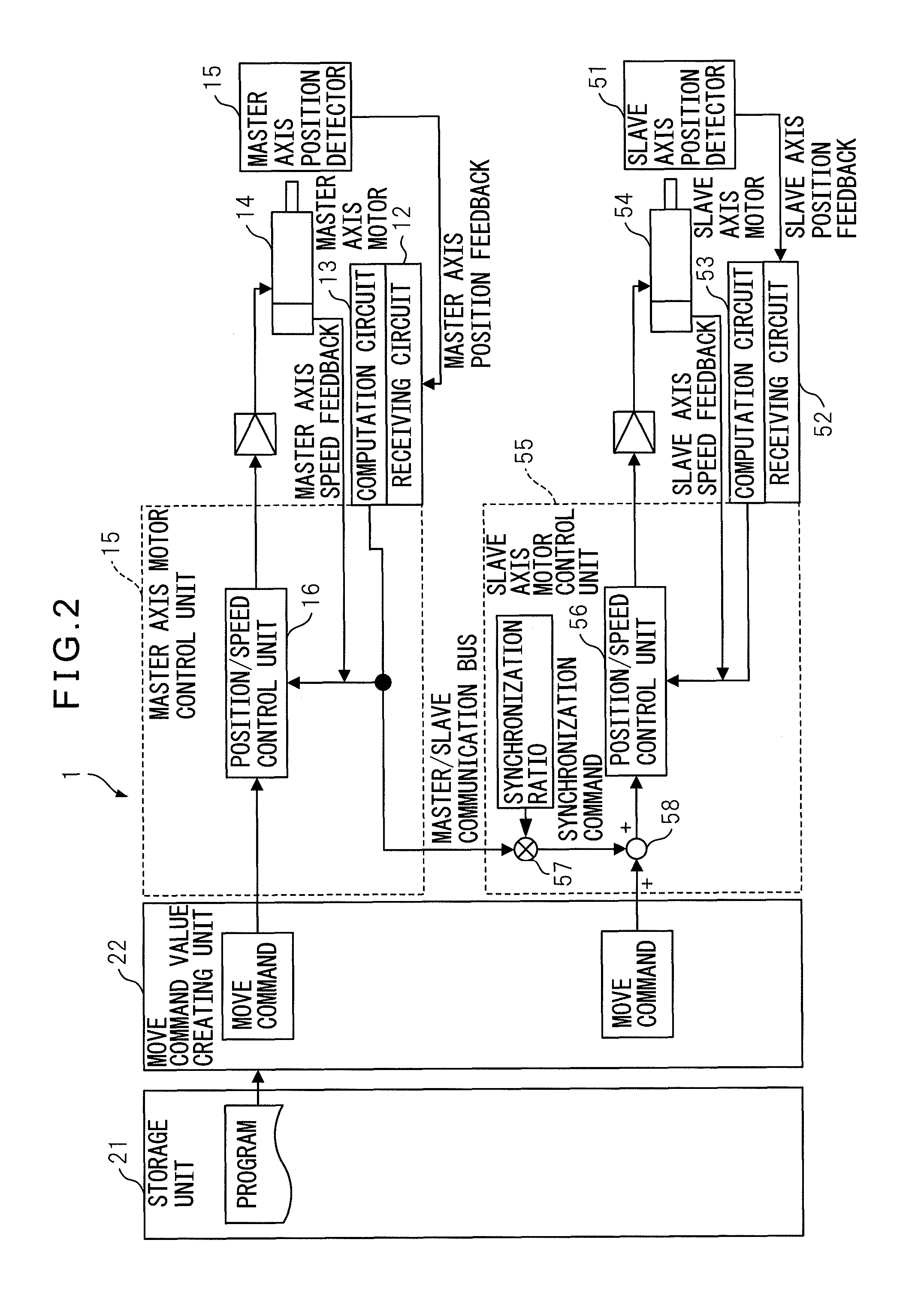
[0034]FIG. 1 is a basic functional block diagram of a motor control apparatus according to an embodiment of the present invention. FIG. 2 is a block diagram showing in further detail the configuration depicted in the basic functional block diagram of FIG. 1. The motor control apparatus 1 according to the embodiment of the present invention can be applied to a machine tool equipped with motors one for each drive axis. For example, the master axis is an axis for driving a tool in a machine, and the slave axis is an axis for driving a workpiece in the machine. In the case of a gear driven machine, for example, the master axis is a tool axis for driving a tool such as a gri...


PUM


Abstract

A motor control apparatus for synchronously controlling a master axis motor for driving a master axis and a slave axis motor for driving a slave axis, includes: a master axis position detector which outputs position data of the master axis and a reference signal with a predetermined fixed period; a master axis receiving circuit which receives the position data and the reference signal output from the master axis position detector; a master axis computation circuit which computes a master axis error representing a difference between the position data received by the master axis receiving circuit and the position data acquired at the time of the reception of the reference signal; and a slave axis motor control unit which controls the operation of the slave axis motor by using the master axis error as a command for synchronizing the operation of the master axis motor.

Description

BACKGROUND OF THE INVENTION[0001]1. Field of the Invention[0002]The present invention relates to a motor control apparatus for synchronously controlling a master axis motor for driving a master axis and a slave axis motor for driving a slave axis.[0003]2. Description of the Related Art[0004]In a machine tool, motors are provided for each drive axis of a machine tool, and are driven and controlled by a motor control apparatus. The motor control apparatus controls the motor speed, torque, or rotor position of each of the motors that drive the respective drive axes of the machine tool.[0005]FIG. 7 is a diagram for explaining a tool axis and a work axis in a gear driven machine. The drive axes of the gear turning machine include an axis (tool axis) for driving a tool such as a grinding wheel or a cutter and an axis (work axis) for driving a workpiece. The tool axis and the work axis are mechanically coupled together via a work gear.[0006]It is known to provide a master-slave synchronizi...

Claims


Application Information

Patent Timeline
IPC IPC(8): G05B11/32G05B19/18G05D3/00
CPCG05B2219/50218G05B19/416
Inventor TAKAYAMA, KENICHIKAWAMURA, HIROYUKI
Owner FANUC LTD
Learn More