Transmissive display apparatus and operation input method
- Summary
- Abstract
- Description
- Claims
- Application Information
AI Technical Summary
Benefits of technology
Problems solved by technology
Method used
Image

Examples
first embodiment
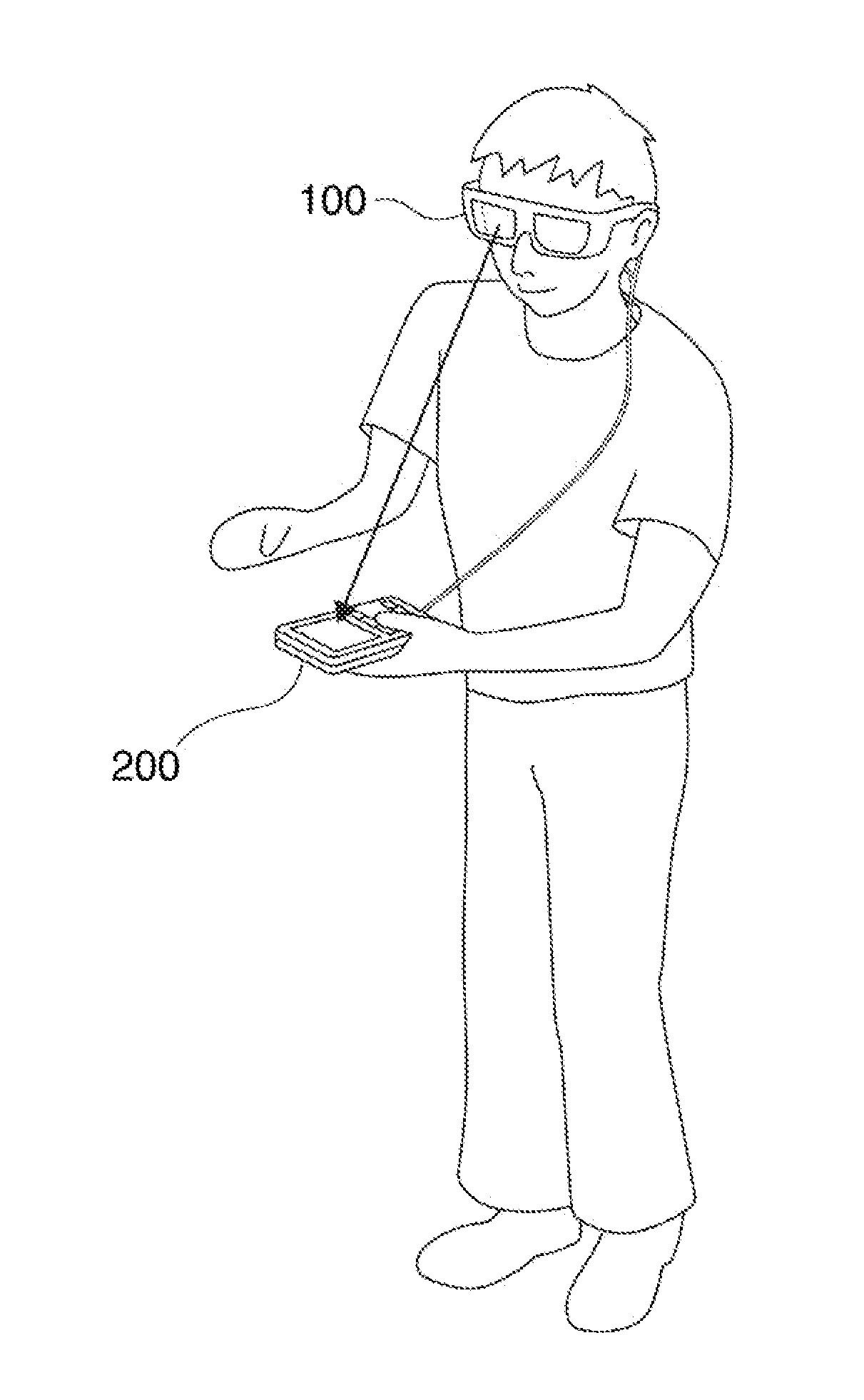
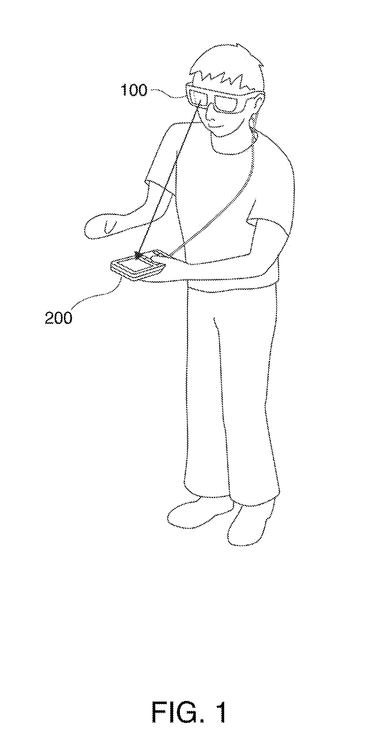
[0036]A first embodiment of the invention will be described in detail with reference to the drawings. FIG. 1 shows a transmissive display apparatus and a user who is using the transmissive display apparatus. The transmissive display apparatus (transmissive head mounted display) includes a display apparatus 100 and a control apparatus 200 (controller).
[0037]A user who wears the display apparatus 100 (of eyeglass type) around the head can view a predetermined image (icon image, menu image, for example) displayed in an image pickup area of an image pickup section of the display apparatus 100. The image pickup area of the display apparatus 100 is configured to transmit at least part of the incident light, whereby the user can view the control apparatus 200 through the image pickup area of the display apparatus 100 with the display apparatus 100 worn around the head. That is, the user can simultaneously observe an optical image formed by the incident light and the displayed predetermined...
second embodiment
[0082]A second embodiment of the invention will be described in detail with reference to the drawings. The second embodiment differs from the first embodiment in that light sources are provided in an enclosure of the control apparatus 200 or the display apparatus 100. Only points different from the first embodiment will be described below.
[0083]FIG. 9 shows an example of the layout of light sources provided in an enclosure of the control apparatus. Light sources 260 are provided in the vicinity of corners of the operation surface and serve as marks showing the position of the operation surface of the operation section 210 of the control apparatus 200. Each of the light sources 260 emits directional infrared light in an out-of-plane direction of the operation surface. Each of the light sources 260 is, for example, a light emitting diode. The light sources 260 may be disposed at opposing corners of the operation surface of the operation section 210 as shown in FIG. 9 or may be dispose...
third embodiment
[0089]A third embodiment of the invention will be described in detail with reference to the drawings. The third embodiment differs from the first and second embodiments in that a key image is superimposed on an optical image of the control apparatus 200. Only points different from the first and second embodiments will be described below.
[0090]FIG. 10 shows an example of display presented when keys are allocated on the operation surface of the operation, section. In FIG. 10, a menu image “QWERTY” and a key image 800 showing a key layout related to the menu image are projected in the image pickup area of the image pickup section 21. Among the keys that form the key image 800, the position of at least one predetermined, key (“Q” and “ENTER” in FIG. 10) is indicated by a frame, whereby the user can specify a position on the operation surface of the operation section 210 (coordinate reference point) to which each predetermined key indicated by the frame is related.
[0091]More specifically...
PUM
 Abstract
Description
Claims
Application Information
 - Generate Ideas
- Intellectual Property
- Life Sciences
- Materials
- Tech Scout
- Unparalleled Data Quality
- Higher Quality Content
- 60% Fewer Hallucinations
Browse by: Latest US Patents, China's latest patents, Technical Efficacy Thesaurus, Application Domain, Technology Topic, Popular Technical Reports.
© 2025 PatSnap. All rights reserved.Legal|Privacy policy|Modern Slavery Act Transparency Statement|Sitemap|About US| Contact US: help@patsnap.com