
Ink-Jet Recording Apparatus

Active Publication Date: 2013-05-30
BROTHER KOGYO KK
View PDF0 Cites 28 Cited by
  • Summary
  • Abstract
  • Description
  • Claims
  • Application Information

AI Technical Summary

Benefits of technology

The patent aims to improve the accuracy of image recording by reducing the distance between the platen and the recording section. This may lead to ink adhering to the contact portion, which then moves to the rear surface of the platen, causing the sheet to become dirty. The technical effect of this invention is improved accuracy of image recording without compromising the quality of the recording apparatus.

Problems solved by technology

As the ink is adhered to the contact portion, the ink moves to a rear surface of the platen from a side of the recording section upon running down a front surface of the contact portion, and makes the sheet dirty.

Method used


Image

  • Ink-Jet Recording Apparatus
  • Ink-Jet Recording Apparatus
  • Ink-Jet Recording Apparatus

Examples


embodiment

Effect of Embodiment

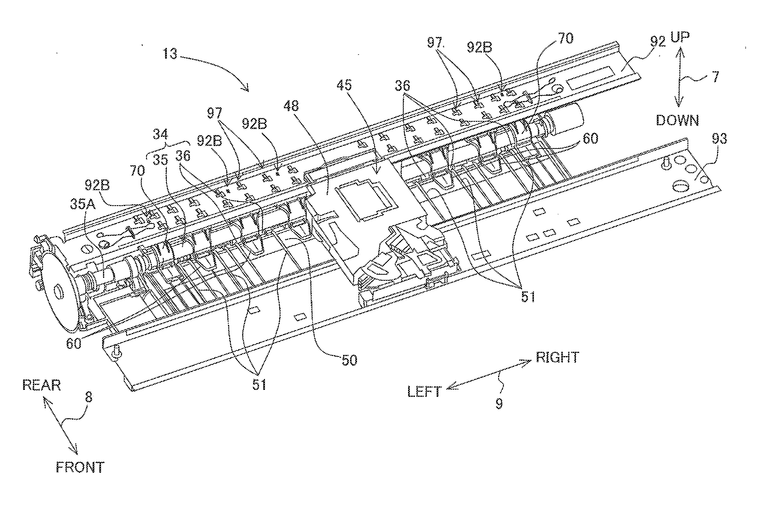
[0086]In the embodiment, the storage section 86 which stores ink is provided on the side of the first surface 81 of the contact portion 63, and the protruding rib 83 which makes a contact with the recording section 45 is provided at the inner side of the surrounding rib 84 which demarcates the storage section 86. Therefore, the ink which has adhered to the protruding rib 83 due to contacting with the recording section 45 flows to the storage section 86 running down the protruding rib 83, and is stored in the storage section 86. By being stored in the storage section 86, the ink is suppressed from flowing toward the second surface 82. As a result, it is possible to suppress the sheet 6 from becoming dirty or stained by the ink which has adhered to the contact members 60 and 70. Accordingly, it is possible to improve the accuracy of image recording by shortening the distance of the gap G in the up-down direction.

[0087]Moreover, since the plurality of ribs 85 is pro...

first modified embodiment

[0088]In the abovementioned embodiment, an example in which the first surface was formed to be a flat surface has been described. In a first modified embodiment, an example in which the first surface 81 is formed to be a curved surface as shown in FIG. 9A will be described. The first surface 81 and the second surface 82 are formed to be circular arc shaped curved surfaces of which a central portion in the left-right direction is positioned at a lower side of a left end and a right end. From the second surface 82, three contact ribs 63 are protruded downward similarly as in the embodiment.

[0089]From the front-end portion of the first surface 81 in the front-rear direction 8, a rib which is not shown in the diagram is protruded upward. This rib is extended up to two ends of the first surface 81 in the left-right direction 9. The storage section 86 is demarcated by this rib and the first surface 81. The protruding rib 83 is provided to be extended in a direction in which the contact po...

second modified embodiment

[0091]In a second modified embodiment, an example in which a plurality of recesses 88B and a plurality of bumps 88A having a hemispherical shape shown in FIG. 9B, instead of the plurality of ribs 85 in the embodiment and the first modified embodiment, are provided to the first surface 81, will be described. The plurality of bumps 88A is protruding upward from the first surface 81. The recesses 88B are dented in the first surface 81. The plurality of bumps 88A and the plurality of recesses 88B are provided on the entire first surface 81. Due to the bumps 88A and the recesses 88B, an area of contact between the contact portion 63 and the ink flowed to the first surface 81 becomes large. As a result, even in a case in which vibrations are imparted to the contact portion 63, it is possible to hold the ink assuredly. When the area of contact can be made large, the bumps 88A and the recesses 88B may be formed to have an arbitrary shape. For instance, the bumps 88A and the recesses 88B may...


PUM


Abstract

There is provided an ink jet recording apparatus which includes a recording portion, and a contact portion configured to come into contact with an upper surface of the sheet. The contact portion has a storage portion provided on a side of the recording portion and configured to store an ink, and a protruding portion is provided between both ends in a width direction intersecting the transporting direction of the storage portion, and which is protruded toward the recording section, and an upper end of the protruding portion is the highest in the contact portion.

Description

CROSS REFERENCE TO RELATED APPLICATION[0001]The present application claims priority from Japanese Patent Application No. 2011-259496, filed on Nov. 28, 2011, the disclosure of which is incorporated herein by reference in its entirety.BACKGROUND OF THE INVENTION[0002]1. Field of the Invention[0003]The present invention relates to an ink jet recording apparatus which records an image on a sheet upon suppressing lifting-off of the sheet from a platen.[0004]2. Description of the Related Art[0005]An ink-jet recording apparatus which includes a platen which supports a sheet transported in a transporting direction (hereinafter, ‘transporting direction’), and which carries out image recording by jetting ink droplets from a recording section onto a sheet on the platen, has hitherto been known. In such type of ink-jet recording apparatuses, there is an apparatus which includes a contact portion which suppresses or inhibits lifting off of a sheet from the platen. The contact portion is arrange...

Claims


Application Information

Patent Timeline
IPC IPC(8): B41J23/00
CPCB41J11/02B41J11/005B41J2/1433
Inventor ITO, TSUYOSHIKOGA, YUJISUGIYAMA, WATARUSAMOTO, KENJI
Owner BROTHER KOGYO KK
Learn More