

Polarization separation device and display apparatus
- Summary
- Abstract
- Description
- Claims
- Application Information
AI Technical Summary
Benefits of technology
Problems solved by technology
Method used
Image

Examples
first embodiment
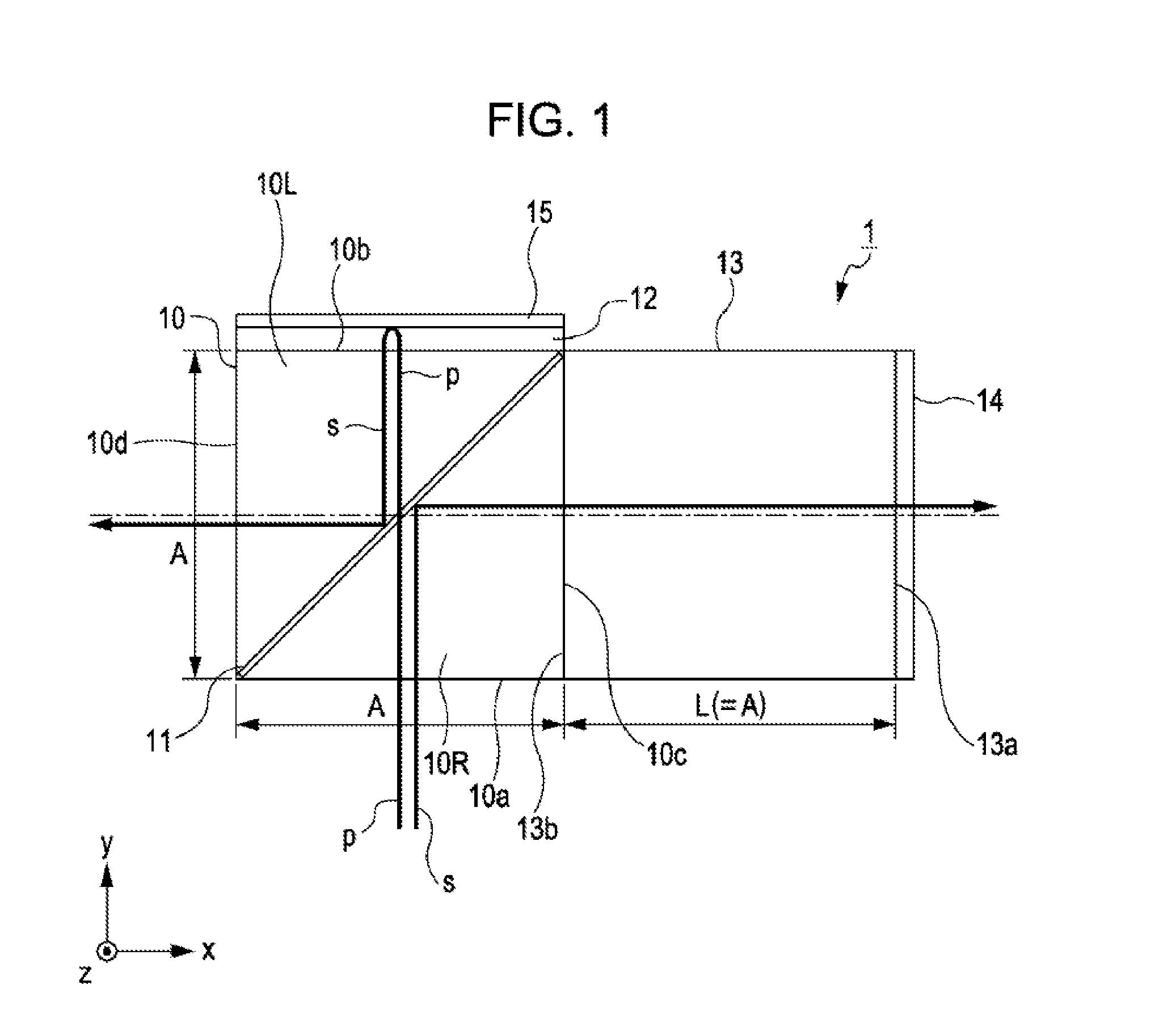
[0031]Hereinafter, various embodiments according to the invention are described with reference to the accompanying drawings. It is to be noted that in the drawings, ratios of dimensions of parts are made different from the actual ratios thereof. Further, the embodiments illustrate one mode of the invention and are not intended to limit the invention. The embodiments can be arbitrarily changed in a range of technical spirit of the invention.
[0032]FIG. 1 is a cross-sectional view illustrating a schematic configuration of a polarization separation device 1 according to the first embodiment of the invention. As illustrated in FIG. 1, the polarization separation device 1 is a device which distributes polarization components of incident light to two directions which are different from the incident direction. The polarization separation device 1 includes a polarization beam splitter 10, a ¼ wavelength film 12, an optical path length adjusting member 13, and a transmissivity adjusting filte...
second embodiment
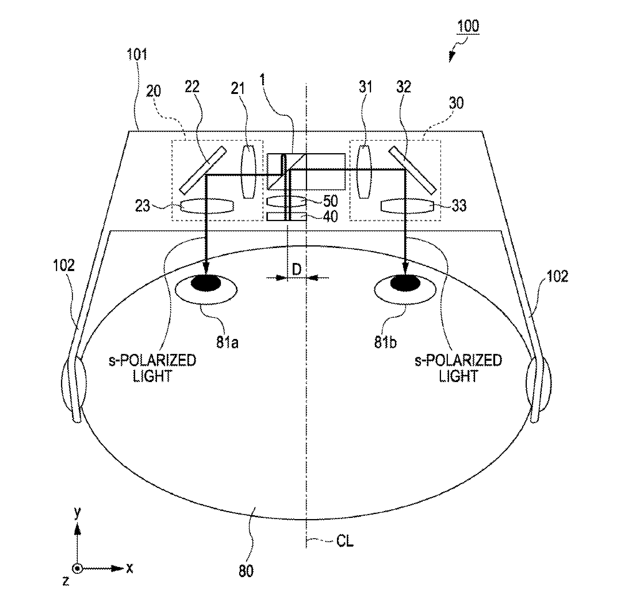
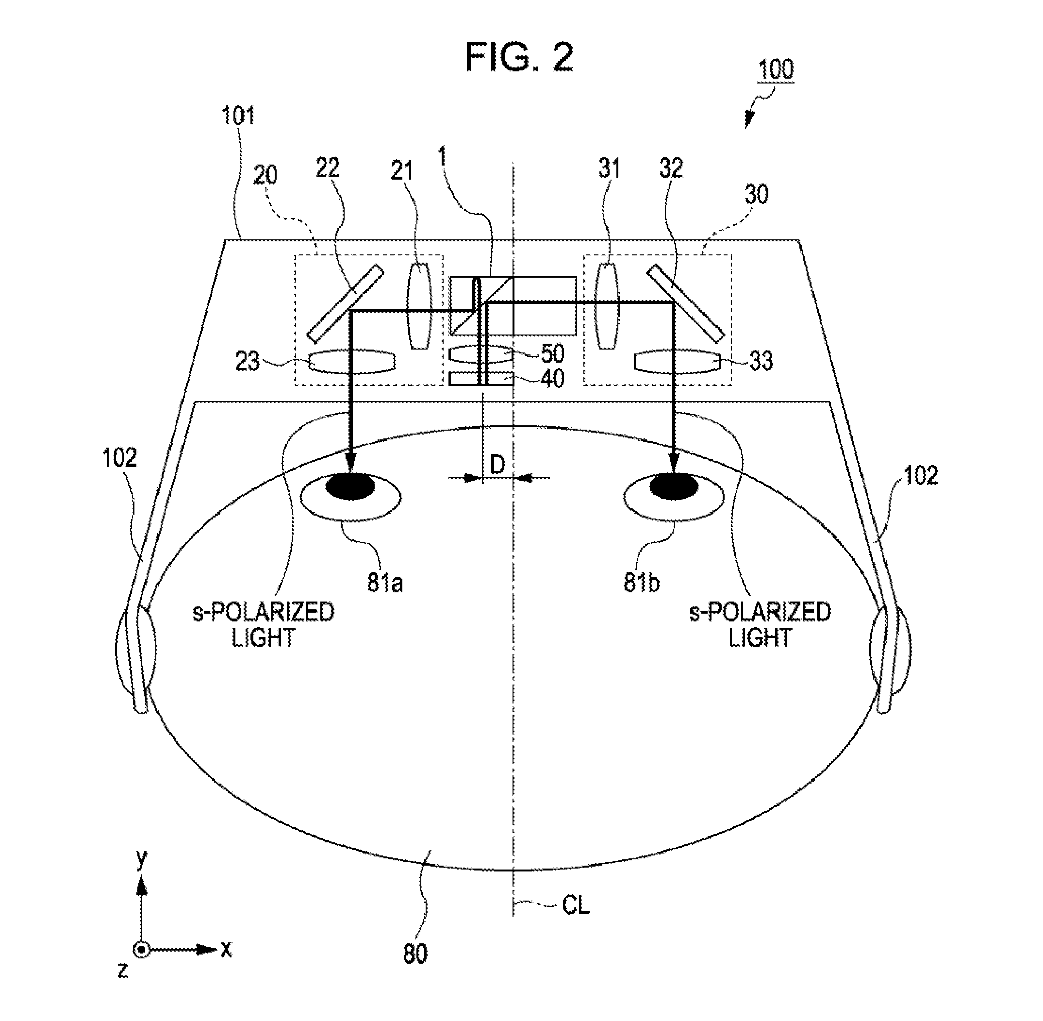
[0049]Next, a head mount display (hereinafter, referred to as HMD) using the polarization separation device 1 having the above-described configuration is described. It is to be noted that in the embodiment, the same reference numerals denote the same constituent components in the above-described first embodiment and the functions and the like thereof are the same unless otherwise specified, and therefore description thereof is omitted.
[0050]FIG. 2 is a descriptive view illustrating a state where an HMD 100 is mounted on a head portion 80 of a person when seen from the above according to the embodiment. FIG. 3 is a top view schematically illustrating an inner configuration of the HMD 100 according to the embodiment. FIG. 4 is a plan view illustrating arrangement of pixels on a display panel 40 according to the embodiment. FIG. 5 is a plan view illustrating arrangement of polarization elements on the display panel 40 according to the embodiment.
[0051]As illustrated in FIG. 2, the HMD ...
third embodiment
[0073]FIG. 7 is a top view schematically illustrating an inner configuration of an HMD 100a according to the third embodiment of the invention. The HMD 100a according to the embodiment is different from the HMD 100 in that the display panel 40 is a liquid crystal display. It is to be noted that in the embodiment, the same reference numerals denote the same constituent components in the above-described first embodiment and second embodiment and the functions and the like thereof are the same unless otherwise specified, and therefore description thereof is omitted.
[0074]A display panel 40a used in the embodiment is a liquid crystal display which can output a polarization component vibrating in the specified direction by a polarization plate at the output side. The pixel array of the display panel 40a is not a special array described in the first embodiment but is a pixel array of the common liquid crystal display, that is, an array in which pixels formed by dots of red, blue and green...
PUM
 Abstract
Description
Claims
Application Information