Split Microwave Backhaul Transceiver Architecture with Coaxial Interconnect

a coaxial interconnection and split microwave technology, applied in the direction of transmitter monitoring, receiver monitoring, transmission monitoring, etc., can solve the problems of inability to properly radiate the antenna, inability to achieve the effect of reducing the cost of coaxial cable routing, and increasing the problem of conventional coaxial cable routing

Active Publication Date: 2013-05-30
MAXLINEAR ASIA SINGAPORE PTE LTD
View PDF16 Cites 33 Cited by
  • Summary
  • Abstract
  • Description
  • Claims
  • Application Information

AI Technical Summary

Problems solved by technology

However, if the antenna were also to be located on the PCB, the antenna would not be able to radiate properly.
The reason for this is that each of these locations allows the antenna to properly radiate, which is not possible when the antenna is located on the PCB along with the radio device.
However, conventional coaxial cable routing becomes more and more of a problem as operation frequency rises.
For example, when the communication system operates at a commonly utilized frequency of 60 GHz, the system does not function properly.
In particular, routing the 60 GHz signal through the coaxial cable results in significant losses and degradation of the signal.

Method used


Image

  • Split Microwave Backhaul Transceiver Architecture with Coaxial Interconnect
  • Split Microwave Backhaul Transceiver Architecture with Coaxial Interconnect
  • Split Microwave Backhaul Transceiver Architecture with Coaxial Interconnect

Examples


Embodiment Construction

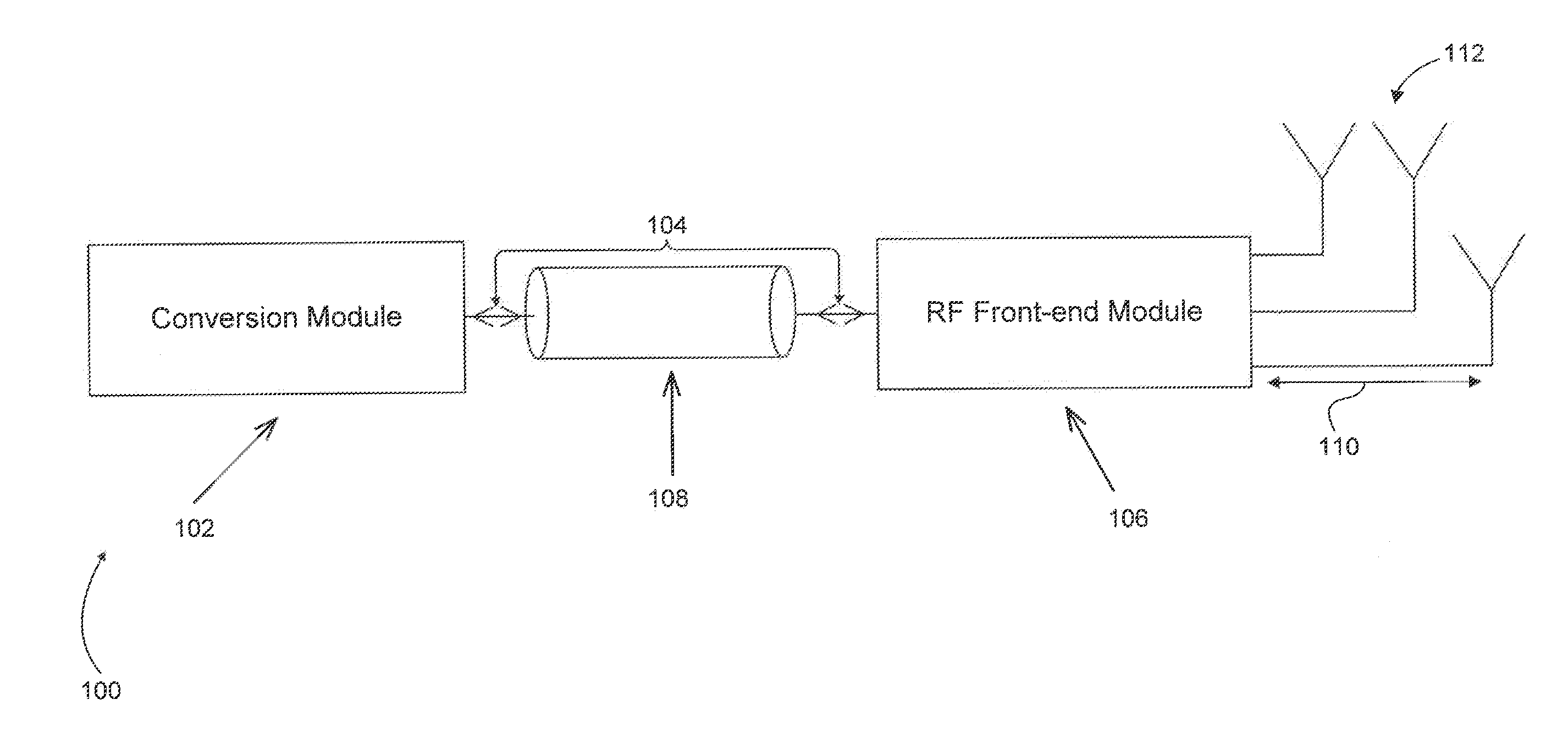
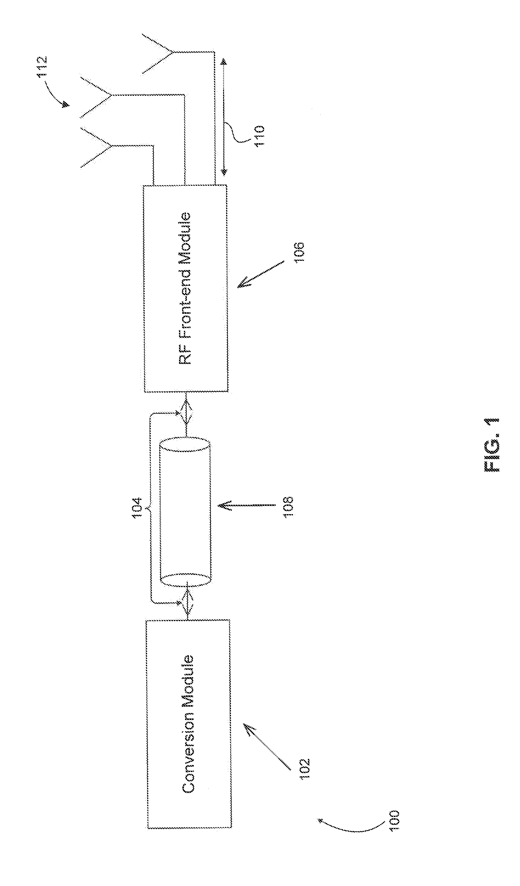
[0016]In computing devices incorporating conventional communication technologies, a coaxial cable may be used to connect a radio device to an antenna. The antenna and the radio device may be located in different areas of the computing device. Typically, a coaxial cable connects the radio device to the antenna. The cable is routed from the radio device, which may be located on a printed circuit board (PCB), through the casing of the computing device and into the periphery of the device. The reason for this routing technique is that the antenna is usually located in the periphery of the computing device so that the antenna can radiate properly, which it would not have been able to do if it were located on the PCB along with the radio device. However, when the communication system operates at a commonly utilized frequency of 60 GHz, the system does not function properly due to significant losses and deterioration of the signal. Thus, there is a need for an alternative, which allows for...


PUM


Abstract

A communication system includes a conversion module configured to convert a signal between a radio frequency baseband (RF-BB) and an intermediate frequency (IF). At least one RF front-end module converts the signal between the IF and a radio frequency (RF). The RF front-end module is configured as an RF phased array and includes a coaxial interconnect configured to connect the conversion module with the RF front-end module. The signal is transmitted between the conversion module and the RF-front end module via the coaxial interconnect. At least one RF front-end module includes an active front-end (AFE) configured to allow the signal to be transmitted via the coaxial interconnect while minimizing any deterioration of the signal.

Description

CROSS REFERENCE TO RELATED APPLICATIONS[0001]This patent application claims the benefit of U.S. Provisional Patent. Application No. 61 / 565,469, filed Nov. 30, 2011, which is incorporated herein by reference in its entirety.BACKGROUND OF THE INVENTION[0002]1. Field of the Invention[0003]The invention relates to a split microwave transceiver, and more specifically to a split microwave transceiver incorporating a coaxial interconnect.[0004]2. Related Art[0005]Local area networks (LANs) and systems incorporating Bluetooth or WiFi technology have recently become widely implemented communication technologies, especially in personal computing devices. Typical implementations of these conventional technologies, as well as other communication technologies, include an antenna connected to a radio device using a coaxial cable. The radio device is normally located on a printed circuit board (PCB) within the computing device. However, if the antenna were also to be located on the PCB, the antenn...

Claims


Application Information

Patent Timeline
Patent Type & Authority Applications(United States)
IPC IPC(8): H04B17/00H04B1/38
CPCH04L5/143H04L27/368H04L27/02H04L5/1461H04B17/13H04B17/14H04B17/21H04B1/26H04B1/56
Inventor VASSILIOU, IASONBOERS, MICHAELNICOLSON, SEANIBRAHIM, BRIMAKAVVADIAS, SPYRIDON
Owner MAXLINEAR ASIA SINGAPORE PTE LTD
Why Eureka
Try Eureka