Butler matrix for 3D integrated RF front-ends

a butler matrix and front-end technology, applied in the field of electromagnetic devices, can solve the problems of high cost and bulky conventional radars, and achieve the effect of low loss r

Active Publication Date: 2010-09-09
TOYOTA MOTOR CO LTD
View PDF24 Cites 62 Cited by
  • Summary
  • Abstract
  • Description
  • Claims
  • Application Information

AI Technical Summary

Benefits of technology

[0003]Embodiments of the present invention relate to microwave applications, in particular millimeter wave antennas including automotive radar antennas. Examples of the present invention include improved apparatus and methods for includ

Problems solved by technology

However, conventional rada

Method used


Image

  • Butler matrix for 3D integrated RF front-ends
  • Butler matrix for 3D integrated RF front-ends
  • Butler matrix for 3D integrated RF front-ends

Examples


Embodiment Construction

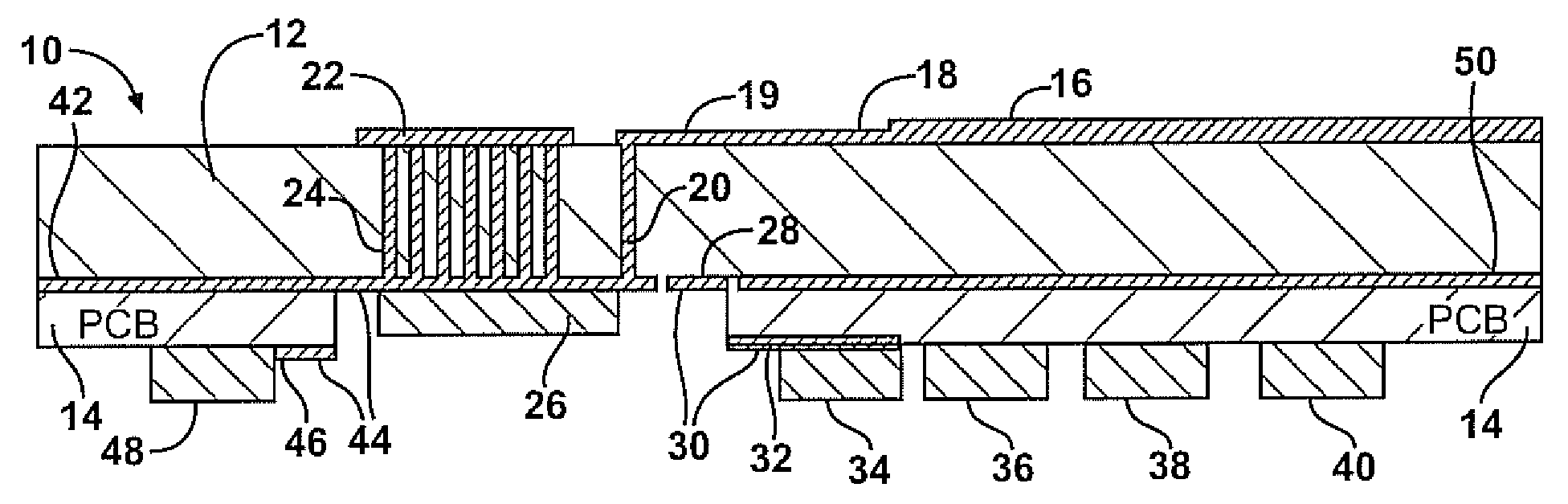
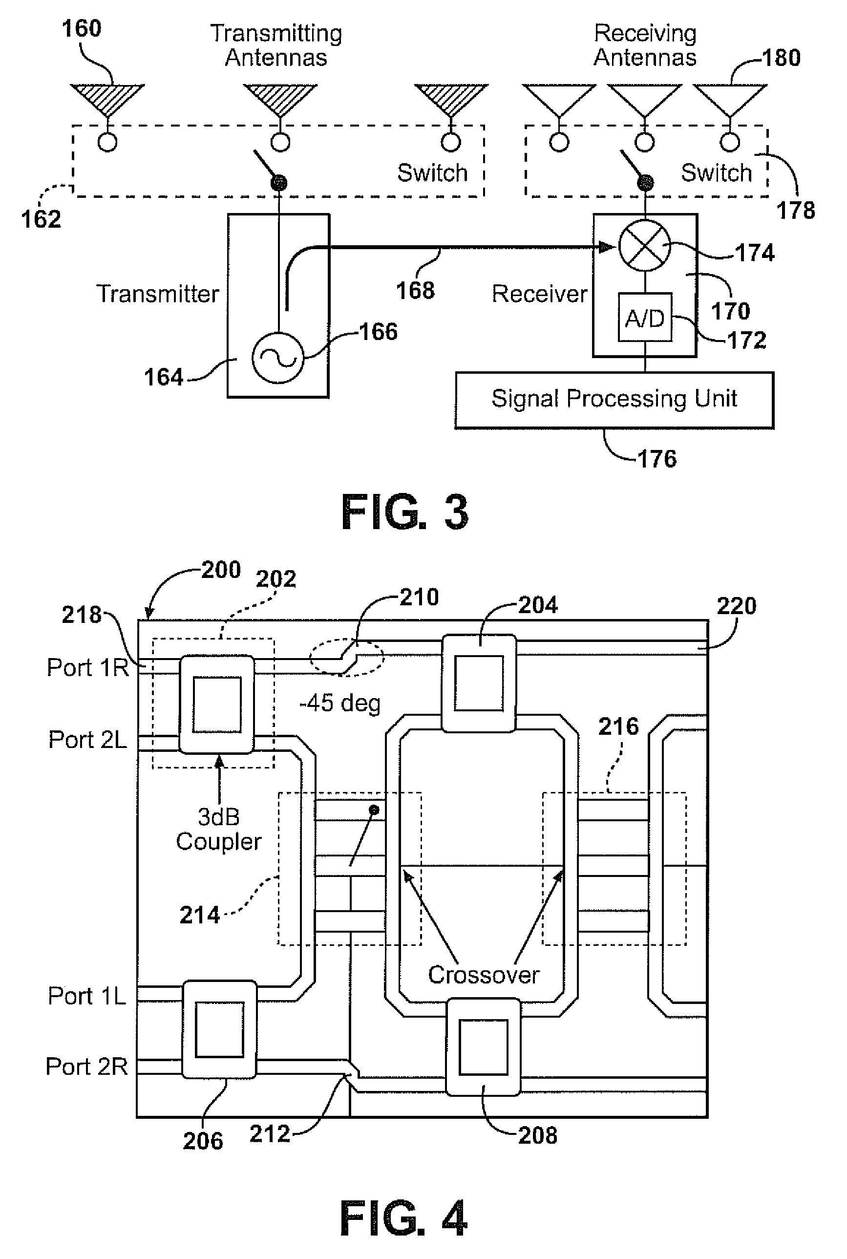
[0033]Examples of the invention include apparatus and methods relating to the use of a 3D integrated Butler matrix for radar applications. A Butler matrix can be used in electronically scanned antennas, e.g. for antenna beam steering. A Butler matrix can be used to generate a set of predefined beams, and allows switching between the beams in order to point a radar beam in a specific direction. Hence, examples of the present invention include steerable radar devices.

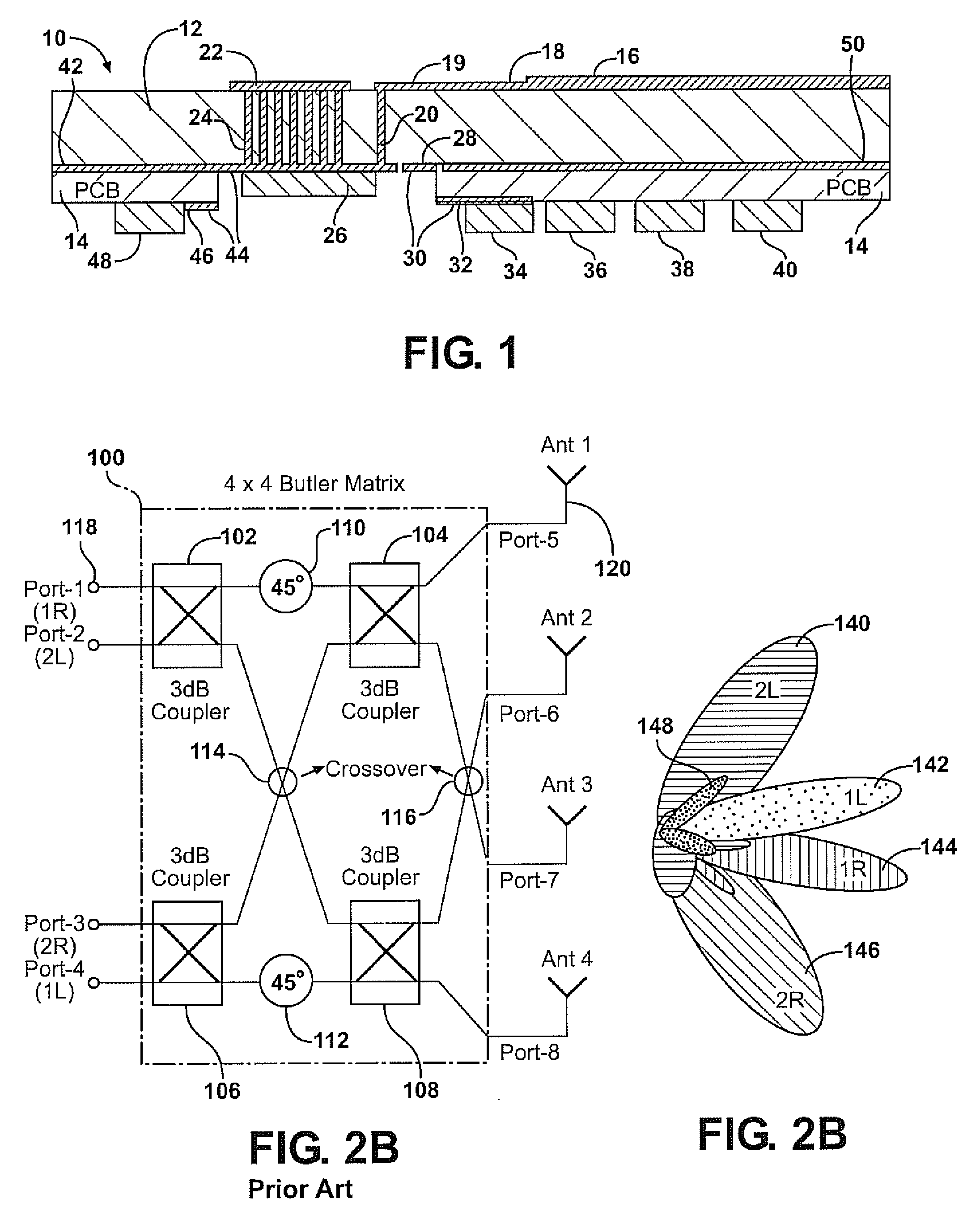
[0034]A Butler matrix may be a fully-passive mm-wave circuit that includes hybrid couplers, phase delay lines and crossovers, and can transform signals from N antenna elements to a set of N beams. Planar configurations of the Butler matrix can have the advantage of easier manufacturing process and lower cost. However, the crossover region in the Butler matrix becomes a challenge.

[0035]Examples of the present invention include a Butler matrix designed for operation at 77 GHz, for automotive radar applications. A 77 GHz des...


PUM


Abstract

Examples of the present invention include a radar apparatus comprising a substrate, an antenna disposed on a first side of the substrate, a Butler matrix supported by same the substrate, output ports of the Butler matrix being electrically connected with a group of radiative elements; and input ports configured to be in communication with a radio frequency (RF) circuit. The RF circuit may be supported proximate or adjacent the substrate.

Description

FIELD OF THE INVENTION[0001]The invention relates to electromagnetic devices, for example radar antennas.BACKGROUND OF THE INVENTION[0002]Antennas are useful for a variety of applications, for example automotive radar applications. A low cost antenna having a steerable beam is highly desirable. However, conventional radars are expensive and bulky.SUMMARY OF THE INVENTION[0003]Embodiments of the present invention relate to microwave applications, in particular millimeter wave antennas including automotive radar antennas. Examples of the present invention include improved apparatus and methods for including a Butler matrix between an RF circuit and an antenna. Examples of the present invention include a low loss RF substrate for microwave and / or millimeter wave applications, the substrate supporting an antenna array and a Butler matrix.[0004]A Butler matrix can be formed as a multi-layer structure, such as a two-layer structure on a sheet-like substrate, which significantly reduces th...

Claims


Application Information

Patent Timeline
IPC IPC(8): G01S13/00H01Q3/00
CPCG01S7/032H01Q21/065H01Q3/40G01S13/931
Inventor MARGOMENOS, ALEXANDROSDING, RUIHUA
Owner TOYOTA MOTOR CO LTD
Why Eureka
Try Eureka